- Tech Alert: Why Your Minn Kota Terrova is Blowing Control Boards on Lithium Power
- Advanced Armature Testing for Electric Trolling Motors: A Comprehensive Diagnostic Guide
- The Effortless Angler: A Guide to Mastering the Minn Kota Ulterra
- Unlocking Your Tilt: The Definitive Guide to Changing the T-Bar Tilt Pin on a Minn Kota Trolling Motor
- Cut Down to Size: A Detailed Guide on How to Shorten Your Minn Kota Trolling Motor Shaft
- Prop Replacement: A Detailed Guide to Maintaining Your Minn Kota Trolling Motor
- Powering Your Trolling Motor: A Comprehensive Guide to 12V, 24V, and 36V Battery Hookups
- Restoring Control: A Detailed Guide to Replacing the 5-Speed Switch on Your Minn Kota Endura Trolling Motor
- How to Clean Up and Repair a Water Leak in Your Minn Kota Trolling Motor
- Unveiling the Phantom Angler: The Lowrance Ghost Trolling Motor
- Bow Mount vs. Transom Mount: Making the Right Trolling Motor Choice
- The Perfect Match: Selecting the Right Quick Release Bracket for Your Minn Kota Trolling Motor
- Getting Your Minn Kota i-Pilot Back on Track: A Troubleshooting and Repair Guide
- Replacing Brushes on Your Minn Kota Trolling Motor
- Keep Your Minn Kota Running Strong: Essential Care for Your Trolling Motor
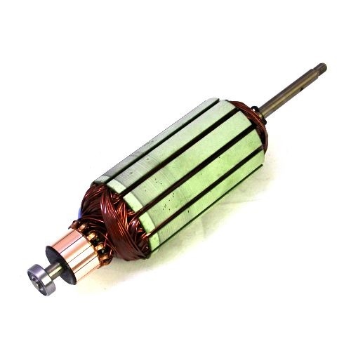
The transition to high-performance, electronically commutated brushless DC (BLDC) motors in modern electric trolling motors has fundamentally changed the requirements for armature diagnostics. The armature, or more accurately the stator in these outrunner designs, is a complex assembly of precision windings, high-grade insulation, and integrated position sensors. Its health is paramount to achieving the silent operation, efficiency, and high thrust demanded by today’s anglers. This article provides a detailed, technical guide to advanced armature testing, moving beyond simple continuity checks to encompass a suite of sophisticated diagnostic procedures. We will cover insulation system analysis, winding integrity verification using surge and resistance tests, and functional testing of integrated Hall effect sensors, providing a complete methodology for identifying and diagnosing armature faults before they lead to catastrophic failure on the water.
1. Introduction: The Evolving Role of the Trolling Motor Armature
In the context of modern BLDC trolling motors, the term “armature” typically refers to the stationary component, the stator, which houses the copper windings. The rotor, containing the permanent magnets, spins around this stator (an “outrunner” configuration). This is a critical distinction from traditional brushed DC motors where the armature rotates.
The BLDC stator is not merely a set of coils; it is an engineered system responsible for generating a precise, rotating magnetic field. Its failure can manifest in several ways:
- Loss of Power/Torque: Caused by shorted windings or poor electrical connections.
- Erratic Operation or “Cogging”: Often linked to sensor failures or shorts between phases.
- Excessive Noise and Vibration: A symptom of winding shorts or electrical imbalances.
- Tripped Breakers or Blown Fuses: Indicative of a direct short to ground.
- Complete Motor Failure: The result of a catastrophic insulation breakdown.
Standard multimeter tests can sometimes detect a dead short, but they are insufficient for identifying the subtle, incipient faults that degrade performance and precede total failure. Advanced testing is required to assess the two primary aspects of armature health: the integrity of the insulation system and the condition of the winding conductors.
2. Pre-Test Considerations and Safety
Before initiating any test, several preparatory steps are crucial for ensuring accurate results and personal safety.
Safety First: All tests involving high voltage (Insulation Resistance, Hi-Pot, Surge) must be conducted with the motor disconnected from its power source and controller. The testing area should be secure, and the operator should use appropriate Personal Protective Equipment (PPE), including high-voltage gloves. Always ensure the windings are fully discharged after testing.
Preparation and Cleaning: The armature should be clean and dry. Contaminants like moisture, salt residue, and oil can create conductive paths on the surface of the windings, leading to misleadingly low insulation resistance readings. If the motor has been recently submerged or exposed to heavy moisture, it should be thoroughly dried in a low-temperature oven or with forced air before testing.
Temperature Correction: The resistance of copper windings and the effectiveness of insulation are temperature-dependent. For accurate, repeatable results, especially for trending motor health over time, all measurements should be temperature-corrected to a standard of 40°C. Many modern testers have a built-in temperature probe and perform this correction automatically. The formula for correcting winding resistance is:
R_c=R_ttimesfrac234.5+T_c234.5+T_t
Where:
- R_c = Corrected Resistance at standard temperature (T_c)
- R_t = Measured Resistance at test temperature (T_t)
- T_c = Standard Temperature (e.g., 40°C)
- T_t = Winding Temperature at time of test (°C)
- 234.5 is the temperature constant for copper.
Test Sequencing: Always perform low-voltage tests (winding resistance, sensor checks) before high-voltage tests. Applying high voltage to a motor with a confirmed short can cause further damage.
3. The Test Battery: A Multi-Faceted Diagnostic Approach
No single test can reveal all potential faults. A comprehensive armature analysis involves a battery of tests, each designed to investigate a specific failure mode.
3.1. Winding Resistance Test (Low Voltage)
This is the most fundamental test, used to verify the uniformity of the windings in each of the three phases (U, V, W) of the BLDC motor.
- Objective: To detect dead shorts, open circuits, or significant imbalances between phases caused by mis-wound coils, poor internal connections, or turn-to-turn shorts that have evolved into a major short.
- Procedure: A digital low-resistance ohmmeter (DLRO) or a quality winding analyzer is used to measure the resistance between each pair of phase leads: U-V, V-W, and W-U.
- Interpretation:
- Good: The three resistance readings should be very low (typically less than 1 ohm) and balanced to within 1-2% of each other.
- Bad (Open): An infinite resistance reading on any phase indicates a broken winding or a failed connection.
- Bad (Short/Imbalance): A resistance reading that is significantly lower than the others or a phase imbalance greater than 3-5% points to a short circuit or a winding error. A significant imbalance creates an uneven magnetic field, leading to vibration and inefficient operation.
3.2. Insulation Resistance (IR) / Megohmmeter Test (High Voltage)
This is the primary test for assessing the integrity of the groundwall insulation—the barrier between the copper windings and the steel stator core (ground).
- Objective: To detect weaknesses, moisture contamination, or cracks in the groundwall insulation that could lead to a phase-to-ground short.
- Procedure: A megohmmeter applies a DC voltage (typically 500V or 1000V for low-voltage motors) between all three shorted-together phase leads and the stator core. The instrument measures the resulting leakage current and displays it as a resistance value in megohms (MΩ).
- Interpretation:
- Pass/Fail Value: A common rule of thumb is that the insulation resistance should be at least 1 MΩ for every kilovolt (kV) of the motor’s operating voltage, plus 1 MΩ. For a 36V trolling motor, a reading below 2 MΩ is considered poor. In reality, a healthy, dry motor should read well in excess of 100 MΩ, often into the gigohm (GΩ) range.
- Polarization Index (PI) and Dielectric Absorption Ratio (DAR): These are advanced IR tests that provide deeper insight into the insulation’s condition.
- PI: The ratio of the 10-minute IR reading to the 1-minute IR reading. A PI value below 2.0 suggests that the insulation is contaminated (e.g., with moisture) or aged.
- DAR: The ratio of the 60-second IR reading to the 30-second IR reading. It provides a quicker check, with a value below 1.25 being questionable. A low PI or DAR reading indicates that the leakage current is not decreasing over time as the insulation polarizes, a sign of contamination that provides a conductive path for current.
3.3. Hi-Pot (High Potential) Test (High Voltage, Proof Test)
The Hi-Pot, or dielectric strength test, is a stress test for the insulation system. While the IR test diagnoses insulation health, the Hi-Pot test confirms its integrity up to a specific voltage level.
- Objective: To determine if the groundwall insulation can withstand a voltage spike without breaking down. This is a go/no-go test.
- Procedure: An AC or DC voltage is applied between the shorted windings and the stator core. The test voltage is typically set to twice the motor’s operating voltage plus 1000V (for new motors). For maintenance testing, this is often reduced to 60-80% of that value. The test measures the leakage current, and if it exceeds a preset trip level, the test fails.
- Interpretation:
- Pass: The insulation withstands the test voltage for the specified duration (usually 60 seconds) without the leakage current exceeding the trip level.
- Fail: A sudden, large rush of current indicates the insulation has broken down and an arc has occurred between the winding and the stator core. This test is potentially destructive and should only be performed when a high degree of assurance is required. It is often performed after a rewind or major repair.
3.4. Surge Test (High Voltage, High Frequency)
The surge test is the only test that can reliably detect issues in the turn-to-turn insulation within a single coil—the most common point of initial winding failure.
- Objective: To find weak turn-to-turn, coil-to-coil, and phase-to-phase insulation.
- Procedure: The tester injects a series of very fast rise-time, high-voltage pulses into two phases at a time, leaving the third phase as a reference. This creates a voltage potential between adjacent turns of the windings. The resulting ringing frequency waveform is captured on an oscilloscope and compared between the phases.
- Interpretation: This is a comparative test. The principle is that all three phases of the motor are identical, so their electrical signatures should be as well.
- Good: The three resulting waveforms (U-V, V-W, W-U) lie perfectly on top of each other. They are identical in shape, frequency, and amplitude.
- Bad (Turn-to-Turn Short): If one phase has a short between turns, the inductance of that winding changes. This will cause its waveform to shift to the left (a lower inductance results in a higher resonant frequency) and have a lower amplitude (due to the energy dissipated in the short). Modern testers calculate the percentage difference in the area under the curves, known as the Error Area Ratio (%EAR), to quantify the imbalance. Even a 1-2% deviation can indicate an incipient fault.
(Conceptual image: A diagram showing two perfectly overlaid ‘good’ surge waveforms and a third, left-shifted and lower-amplitude ‘bad’ waveform indicating a short.)
3.5. Hall Effect Sensor Testing (Low Voltage)
BLDC motors rely on rotor position sensors to time the commutation of the windings. In most trolling motors, these are Hall effect sensors. If the sensors fail or provide incorrect signals, the motor will run erratically or not at all.
- Objective: To verify the correct operation of the integrated Hall effect sensors.
- Procedure:
- Static Test: Power the sensors using a low-voltage DC supply (typically 5V). Connect a voltmeter to the signal output of each of the three sensors (H1, H2, H3). Manually and slowly rotate the motor’s propeller/rotor. As the rotor magnets pass each sensor, the sensor’s output voltage should switch cleanly between a low state (near 0V) and a high state (near 5V).
- Dynamic Test (Oscilloscope): Connect the three sensor outputs to a 3-channel oscilloscope. While rotating the motor at a slow, steady speed, you should observe three square wave patterns. These patterns should be evenly spaced, with a 120° electrical phase shift between them, and should not have any dropouts, glitches, or noise.
- Interpretation:
- Good: Each sensor switches cleanly between high and low states, and the dynamic oscilloscope pattern shows three balanced, 120°-shifted square waves.
- Bad: A sensor that is stuck high or low, or a waveform that is missing or noisy, indicates a failed sensor or a problem with its wiring or connections.
4. Integrated Diagnostic Workflow
For a comprehensive armature analysis, these tests should be performed in a logical sequence.
- Visual Inspection & Cleaning: Check for obvious signs of overheating (discolored varnish), physical damage, or contamination. Clean and dry the armature.
- Sensor Checks (Static & Dynamic): Verify the core commutation control system first.
- Winding Resistance Test: A quick, low-voltage check for gross imbalances or opens.
- Insulation Resistance (IR) Test: Assess the health of the groundwall insulation. Perform a PI or DAR test for a more detailed diagnosis of contamination.
- Surge Test: The definitive test for winding insulation integrity. This will find the turn-to-turn weaknesses that other tests miss.
- Hi-Pot Test (Optional): Use only when required as a final proof test after a repair or rewind.
5. Conclusion: From Reactive Repair to Predictive Maintenance
Advanced armature testing transforms trolling motor repair from a reactive, part-swapping exercise into a precise, scientific process. By understanding and applying this battery of tests, technicians can pinpoint the exact failure mode within an armature, whether it be moisture in the insulation, a short between turns, or a faulty Hall sensor. Furthermore, by recording these measurements over the life of a motor, it becomes possible to trend the degradation of the insulation and winding systems. This data-driven approach enables predictive maintenance, allowing for faults to be identified and addressed during routine service before they cause a critical failure, ensuring that the angler’s investment remains reliable, efficient, and ready for the water.