Tech Alert: Why Your Minn Kota Terrova is Blowing Control Boards on Lithium Power
It’s the upgrade every angler wants: switching from heavy lead-acid batteries to lightweight, high-capacity Lithium Iron Phosphate (LiFePO4). While your boat gets lighter and your runtime extends, a frustrating and costly problem has emerged for many owners of Minn Kota Terrova (and Riptide) trolling motors: fried control boards.
This isn’t just bad luck. It’s a classic engineering conflict between modern power supply tech and legacy motor design.
Here is a technical deep dive into exactly why this happens, how to measure the risk, and how to stop the “blown board” cycle.
The Problem: When 12 Volts Isn’t 12 Volts
The fundamental issue is voltage pressure.
A traditional “12-volt” lead-acid battery is nominal. Fully charged, it’s 12.7V. Under the 50-60A load of a trolling motor, it immediately sags to 12.2V or lower. The Terrova’s internal components (MOSFETs, capacitors) were engineered with this voltage sag in mind.
A 12V lithium battery is different. LiFePO4 cells are rated at 3.2V nominal. A 4-cell pack (standard 12V LiFePO4) sits at 13.4V to 13.6V resting. Crucially, lithium has extremely low internal resistance, meaning it maintains this high voltage under heavy load. It may only drop to 13.0V while pulling max amps.
In 24V or 36V systems, this difference is amplified. The motor, designed for the lower average voltage of lead-acid, is now subjected to sustained “high voltage pressure.”
Why the Boards Blow: Two Technical Failure Points
1. The Inductive “Load Dump” (The Surge that Kills)
This is the main killer. All modern trolling motors use Pulse Width Modulation (PWM)—switching the motor on and off thousands of times per second—to control speed. When the motor is “on,” energy is stored in its powerful magnetic windings.
When you abruptly let off the button, or use the “prop on/off” switch, the PWM duty cycle cuts. The energy in the motor magnets has nowhere to go. This is an inductive voltage spike. It kicks backward into the control board.
With a lead-acid battery, that spike is absorbed. Lead-acid batteries have higher internal resistance and effectively act as a massive capacitor, dampening the surge.
A Lithium battery’s Battery Management System (BMS) introduces a new failure point. If your motor pulls a sudden burst of speed and exceeds the battery’s maximum discharge current rating (e.g., if you have a 50A BMS but the motor spikes to 60A), the BMS triggers an instantaneous over-current shutdown. It goes from ON to OPEN in milliseconds.
If the BMS cuts power while the motor is spinning, the massive inductive surge is trapped between the motor and the now-open battery circuit. The surge (often exceeding 60V) slams into the motor control board, instantaneously exceeding the voltage rating of the sensitive MOSFETs (transistors) and capacitors. Result: Instant death of the steering or main board.
2. Thermal Runaway (The Slow Death)
Running at high voltage (13.6V vs 12.2V) means more current flows through the motor. (Ohm’s Law: Power = V² / R). The system is under higher electrical stress. Running a Terrova at Speed 10 on Lithium generates significantly more heat than Speed 10 on lead-acid.
The components on the control board (especially the steering circuits) overheat. Eventually, the solder melts, or a trace on the PCB delaminates, causing failure.
How to Diagnose If Your Setup Is at Risk
You can often see this risk before a failure occurs. Get a multimeter and measure voltage at the trolling motor plug, while the motor is running on high speed (Speed 10).
Safe (Lead-Acid equivalent): Under load, voltage sags below 12.5V (or 25V/37.5V).
At Risk (Typical Lithium): Under load, voltage remains constant at >13.0V (or 26V/39V).
The Red Zone: If your motor plug gets hot after just a minute of use, you have excessive resistance (bad wiring/plug) causing heat build-up that will eventually pop the board.
The Solution: How to Stop Blowing Boards
If you want to run lithium, you must add components to manage the power difference.
Modification
Why You Need It
Technical Impact
Bussmann 60A Breaker (Manual Reset)
Replace cheap auto-reset or generic breakers. A quality marine breaker reacts instantly to a short, often saving the board before the BMS shuts down.
Faster trip time (t<100ms) prevents over-current damage from sustained high speed.
6-Gauge Marine Grade Wiring
Thicker wire reduces electrical resistance and voltage sag. Paradoxically, less voltage sag (meaning more voltage at the motor) is safer than heat-generating resistance at the plug.
Prevents local overheating and voltage fluctuation that can scramble the i-Pilot/GPS logic.
TVS Diode (Transient Voltage Suppressor)
Highly Recommended. A Bi-directional TVS diode, installed right at the trolling motor plug (between + and -), is designed to clamp inductive surges.
Shunts the voltage spike safely back to the battery, protecting the sensitive board components from the “load dump.”
Limit Speed 10 Usage
Treat Speed 8.5 as your new “Speed 10” for continuous operation. Avoid sudden “0 to Full Throttle” bursts.
Reduces continuous thermal load on the MOSFETs, staying within design tolerances.
By installing a high-quality breaker and a surge-clamping TVS diode, and ensuring your wiring is adequate, you can finally enjoy the lightweight benefits of lithium power without sacrificing your Terrova’s control boards.
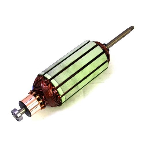
The transition to high-performance, electronically commutated brushless DC (BLDC) motors in modern electric trolling motors has fundamentally changed the requirements for armature diagnostics. The armature, or more accurately the stator in these outrunner designs, is a complex assembly of precision windings, high-grade insulation, and integrated position sensors. Its health is paramount to achieving the silent operation, efficiency, and high thrust demanded by today’s anglers. This article provides a detailed, technical guide to advanced armature testing, moving beyond simple continuity checks to encompass a suite of sophisticated diagnostic procedures. We will cover insulation system analysis, winding integrity verification using surge and resistance tests, and functional testing of integrated Hall effect sensors, providing a complete methodology for identifying and diagnosing armature faults before they lead to catastrophic failure on the water.
1. Introduction: The Evolving Role of the Trolling Motor Armature
In the context of modern BLDC trolling motors, the term “armature” typically refers to the stationary component, the stator, which houses the copper windings. The rotor, containing the permanent magnets, spins around this stator (an “outrunner” configuration). This is a critical distinction from traditional brushed DC motors where the armature rotates.
The BLDC stator is not merely a set of coils; it is an engineered system responsible for generating a precise, rotating magnetic field. Its failure can manifest in several ways:
Loss of Power/Torque: Caused by shorted windings or poor electrical connections.
Erratic Operation or “Cogging”: Often linked to sensor failures or shorts between phases.
Excessive Noise and Vibration: A symptom of winding shorts or electrical imbalances.
Tripped Breakers or Blown Fuses: Indicative of a direct short to ground.
Complete Motor Failure: The result of a catastrophic insulation breakdown.
Standard multimeter tests can sometimes detect a dead short, but they are insufficient for identifying the subtle, incipient faults that degrade performance and precede total failure. Advanced testing is required to assess the two primary aspects of armature health: the integrity of the insulation system and the condition of the winding conductors.
2. Pre-Test Considerations and Safety
Before initiating any test, several preparatory steps are crucial for ensuring accurate results and personal safety.
Safety First: All tests involving high voltage (Insulation Resistance, Hi-Pot, Surge) must be conducted with the motor disconnected from its power source and controller. The testing area should be secure, and the operator should use appropriate Personal Protective Equipment (PPE), including high-voltage gloves. Always ensure the windings are fully discharged after testing.
Preparation and Cleaning: The armature should be clean and dry. Contaminants like moisture, salt residue, and oil can create conductive paths on the surface of the windings, leading to misleadingly low insulation resistance readings. If the motor has been recently submerged or exposed to heavy moisture, it should be thoroughly dried in a low-temperature oven or with forced air before testing.
Temperature Correction: The resistance of copper windings and the effectiveness of insulation are temperature-dependent. For accurate, repeatable results, especially for trending motor health over time, all measurements should be temperature-corrected to a standard of 40°C. Many modern testers have a built-in temperature probe and perform this correction automatically. The formula for correcting winding resistance is:
R_c=R_ttimesfrac234.5+T_c234.5+T_t
Where:
R_c = Corrected Resistance at standard temperature (T_c)
R_t = Measured Resistance at test temperature (T_t)
T_c = Standard Temperature (e.g., 40°C)
T_t = Winding Temperature at time of test (°C)
234.5 is the temperature constant for copper.
Test Sequencing: Always perform low-voltage tests (winding resistance, sensor checks) before high-voltage tests. Applying high voltage to a motor with a confirmed short can cause further damage.
3. The Test Battery: A Multi-Faceted Diagnostic Approach
No single test can reveal all potential faults. A comprehensive armature analysis involves a battery of tests, each designed to investigate a specific failure mode.
3.1. Winding Resistance Test (Low Voltage)
This is the most fundamental test, used to verify the uniformity of the windings in each of the three phases (U, V, W) of the BLDC motor.
Objective: To detect dead shorts, open circuits, or significant imbalances between phases caused by mis-wound coils, poor internal connections, or turn-to-turn shorts that have evolved into a major short.
Procedure: A digital low-resistance ohmmeter (DLRO) or a quality winding analyzer is used to measure the resistance between each pair of phase leads: U-V, V-W, and W-U.
Interpretation:
Good: The three resistance readings should be very low (typically less than 1 ohm) and balanced to within 1-2% of each other.
Bad (Open): An infinite resistance reading on any phase indicates a broken winding or a failed connection.
Bad (Short/Imbalance): A resistance reading that is significantly lower than the others or a phase imbalance greater than 3-5% points to a short circuit or a winding error. A significant imbalance creates an uneven magnetic field, leading to vibration and inefficient operation.
3.2. Insulation Resistance (IR) / Megohmmeter Test (High Voltage)
This is the primary test for assessing the integrity of the groundwall insulation—the barrier between the copper windings and the steel stator core (ground).
Objective: To detect weaknesses, moisture contamination, or cracks in the groundwall insulation that could lead to a phase-to-ground short.
Procedure: A megohmmeter applies a DC voltage (typically 500V or 1000V for low-voltage motors) between all three shorted-together phase leads and the stator core. The instrument measures the resulting leakage current and displays it as a resistance value in megohms (MΩ).
Interpretation:
Pass/Fail Value: A common rule of thumb is that the insulation resistance should be at least 1 MΩ for every kilovolt (kV) of the motor’s operating voltage, plus 1 MΩ. For a 36V trolling motor, a reading below 2 MΩ is considered poor. In reality, a healthy, dry motor should read well in excess of 100 MΩ, often into the gigohm (GΩ) range.
Polarization Index (PI) and Dielectric Absorption Ratio (DAR): These are advanced IR tests that provide deeper insight into the insulation’s condition.
PI: The ratio of the 10-minute IR reading to the 1-minute IR reading. A PI value below 2.0 suggests that the insulation is contaminated (e.g., with moisture) or aged.
DAR: The ratio of the 60-second IR reading to the 30-second IR reading. It provides a quicker check, with a value below 1.25 being questionable. A low PI or DAR reading indicates that the leakage current is not decreasing over time as the insulation polarizes, a sign of contamination that provides a conductive path for current.
3.3. Hi-Pot (High Potential) Test (High Voltage, Proof Test)
The Hi-Pot, or dielectric strength test, is a stress test for the insulation system. While the IR test diagnoses insulation health, the Hi-Pot test confirms its integrity up to a specific voltage level.
Objective: To determine if the groundwall insulation can withstand a voltage spike without breaking down. This is a go/no-go test.
Procedure: An AC or DC voltage is applied between the shorted windings and the stator core. The test voltage is typically set to twice the motor’s operating voltage plus 1000V (for new motors). For maintenance testing, this is often reduced to 60-80% of that value. The test measures the leakage current, and if it exceeds a preset trip level, the test fails.
Interpretation:
Pass: The insulation withstands the test voltage for the specified duration (usually 60 seconds) without the leakage current exceeding the trip level.
Fail: A sudden, large rush of current indicates the insulation has broken down and an arc has occurred between the winding and the stator core. This test is potentially destructive and should only be performed when a high degree of assurance is required. It is often performed after a rewind or major repair.
3.4. Surge Test (High Voltage, High Frequency)
The surge test is the only test that can reliably detect issues in the turn-to-turn insulation within a single coil—the most common point of initial winding failure.
Objective: To find weak turn-to-turn, coil-to-coil, and phase-to-phase insulation.
Procedure: The tester injects a series of very fast rise-time, high-voltage pulses into two phases at a time, leaving the third phase as a reference. This creates a voltage potential between adjacent turns of the windings. The resulting ringing frequency waveform is captured on an oscilloscope and compared between the phases.
Interpretation: This is a comparative test. The principle is that all three phases of the motor are identical, so their electrical signatures should be as well.
Good: The three resulting waveforms (U-V, V-W, W-U) lie perfectly on top of each other. They are identical in shape, frequency, and amplitude.
Bad (Turn-to-Turn Short): If one phase has a short between turns, the inductance of that winding changes. This will cause its waveform to shift to the left (a lower inductance results in a higher resonant frequency) and have a lower amplitude (due to the energy dissipated in the short). Modern testers calculate the percentage difference in the area under the curves, known as the Error Area Ratio (%EAR), to quantify the imbalance. Even a 1-2% deviation can indicate an incipient fault.
(Conceptual image: A diagram showing two perfectly overlaid ‘good’ surge waveforms and a third, left-shifted and lower-amplitude ‘bad’ waveform indicating a short.)
3.5. Hall Effect Sensor Testing (Low Voltage)
BLDC motors rely on rotor position sensors to time the commutation of the windings. In most trolling motors, these are Hall effect sensors. If the sensors fail or provide incorrect signals, the motor will run erratically or not at all.
Objective: To verify the correct operation of the integrated Hall effect sensors.
Procedure:
Static Test: Power the sensors using a low-voltage DC supply (typically 5V). Connect a voltmeter to the signal output of each of the three sensors (H1, H2, H3). Manually and slowly rotate the motor’s propeller/rotor. As the rotor magnets pass each sensor, the sensor’s output voltage should switch cleanly between a low state (near 0V) and a high state (near 5V).
Dynamic Test (Oscilloscope): Connect the three sensor outputs to a 3-channel oscilloscope. While rotating the motor at a slow, steady speed, you should observe three square wave patterns. These patterns should be evenly spaced, with a 120° electrical phase shift between them, and should not have any dropouts, glitches, or noise.
Interpretation:
Good: Each sensor switches cleanly between high and low states, and the dynamic oscilloscope pattern shows three balanced, 120°-shifted square waves.
Bad: A sensor that is stuck high or low, or a waveform that is missing or noisy, indicates a failed sensor or a problem with its wiring or connections.
4. Integrated Diagnostic Workflow
For a comprehensive armature analysis, these tests should be performed in a logical sequence.
Visual Inspection & Cleaning: Check for obvious signs of overheating (discolored varnish), physical damage, or contamination. Clean and dry the armature.
Sensor Checks (Static & Dynamic): Verify the core commutation control system first.
Winding Resistance Test: A quick, low-voltage check for gross imbalances or opens.
Insulation Resistance (IR) Test: Assess the health of the groundwall insulation. Perform a PI or DAR test for a more detailed diagnosis of contamination.
Surge Test: The definitive test for winding insulation integrity. This will find the turn-to-turn weaknesses that other tests miss.
Hi-Pot Test (Optional): Use only when required as a final proof test after a repair or rewind.
5. Conclusion: From Reactive Repair to Predictive Maintenance
Advanced armature testing transforms trolling motor repair from a reactive, part-swapping exercise into a precise, scientific process. By understanding and applying this battery of tests, technicians can pinpoint the exact failure mode within an armature, whether it be moisture in the insulation, a short between turns, or a faulty Hall sensor. Furthermore, by recording these measurements over the life of a motor, it becomes possible to trend the degradation of the insulation and winding systems. This data-driven approach enables predictive maintenance, allowing for faults to be identified and addressed during routine service before they cause a critical failure, ensuring that the angler’s investment remains reliable, efficient, and ready for the water.
In the world of angling technology, few innovations have so dramatically reduced physical effort and increased on-the-water efficiency as the Minn Kota Ulterra. This isn’t just a trolling motor; it’s a robotic fishing partner designed to handle the strenuous tasks of deployment, stowage, and depth adjustment with the simple push of a button. For anglers with mobility challenges, those who frequently fish alone, or anyone who values seamless boat control, the Ulterra represents a paradigm shift.
This lengthy, detailed guide will explore every facet of using the Minn Kota Ulterra, from its groundbreaking core features and control options to advanced fishing strategies empowered by its i-Pilot Link integration. By understanding its full capabilities, you can transform your boat control and focus solely on what matters most: catching fish.
Part 1: The Ulterra Revolution – Understanding the Core Features
What sets the Ulterra apart from every other trolling motor on the market are its three signature automated functions. These features eliminate the need to ever physically handle the motor during a fishing trip.
1. Auto Stow and Deploy
This is the feature that defines the Ulterra. Gone are the days of leaning precariously over the bow, heaving a heavy, wet motor out of the water, or wrestling it back onto its mount.
Deployment: With a double-tap of the deploy button on your remote or foot pedal, the Ulterra gracefully lifts itself from its horizontal stowed position, pivots vertically, and lowers itself into the water to a pre-set depth.
Stowage: A single press of the stow button initiates the reverse sequence. The motor automatically trims up to its highest position, lifts itself vertically out of the water, and powers itself down into its secure cradle on the bow mount, ready for the run back to the dock.
This hands-free operation is a game-changer in rough water, when fishing solo, or when a fish is on the line and you need to quickly stow the motor to move.
2. Power Trim
Traditionally, adjusting the depth of your trolling motor required manually loosening a collar and sliding the heavy shaft up or down. The Ulterra’s Power Trim automates this process entirely.
Using the up and down arrows on the remote or foot pedal, you can raise or lower the motor’s depth with precision. This is invaluable for:
Navigating Shallow Water: Instantly raise the motor to clear submerged logs, rocks, or shallow flats without ever leaving the console.
Adapting to Chop: In rough conditions, you can lower the motor deeper into the water to prevent the propeller from cavitating (coming out of the water) on wave crests, ensuring consistent thrust.
Fine-Tuning Presentation: Maintain the perfect depth for optimal performance of features like MEGA Down Imaging, which is often integrated into the motor’s lower unit.
3. i-Pilot and i-Pilot Link: The GPS Brain
While Auto Stow/Deploy and Power Trim are the physical “muscle,” the i-Pilot or i-Pilot Link system is the “brain.” This GPS-powered navigation system unlocks a suite of automated boat control features that are the cornerstone of modern angling.
Spot-Lock: The most revered feature in all of trolling motor technology. When you find a piece of structure or a school of fish, pressing the Spot-Lock button turns your motor into a virtual anchor. The GPS receiver will automatically keep your boat positioned on that exact coordinate, compensating for wind, waves, and current. You can fish with your hands and feet completely free, without ever drifting off your spot. The Ulterra also features “Jog,” which allows you to move your Spot-Lock location five feet in any direction with the simple push of a button.
AutoPilot: This function allows you to point the motor in a desired direction and it will automatically maintain that heading, correcting for wind and current. It’s the modern equivalent of a compass heading.
Cruise Control: Set a specific speed and the motor will maintain it, automatically adjusting propeller power to compensate for wind or current. This is essential for precise trolling presentations.
iTracks: Record a fishing path (up to two miles long) and save it to the system’s memory. You can then command the motor to automatically retrace that path later, perfectly replicating a successful trolling run.
Part 2: Your Command Center – Controlling the Ulterra
You have three primary methods for controlling your Ulterra, each suited to different fishing styles.
1. The Wireless Remote (i-Pilot or i-Pilot Link)
This is your master control. The modern touch-screen i-Pilot Link remote is like a smartphone for your trolling motor. From this remote you can access every function:
Stow and Deploy: Dedicated buttons for hands-free operation.
Power Trim: Up and down arrows for depth adjustment.
Steering: Left and right arrows to manually steer the motor.
Prop Speed: Plus and minus buttons to increase or decrease speed.
Spot-Lock and AutoPilot: One-touch activation buttons.
High Speed Bypass: Instantly puts the prop at full power (level 10) for quick maneuvers.
2. The Wireless Foot Pedal
For the angler who prefers hands-free control while casting from the bow, the wireless foot pedal is indispensable. It offers a unique “heel/toe” steering system and dedicated buttons for critical functions.
Heel/Toe Steering: Press the toe down to turn right, the heel down to turn left.
Constant On/Momentary: A side button toggles between momentary mode (prop only spins while you have your foot on the pedal) and constant mode (prop stays on at the set speed).
Spot-Lock Button: A dedicated button to instantly engage your virtual anchor.
Auto Stow/Deploy Button: A user-programmable button that can be set to either stow/deploy the motor or activate AutoPilot.
3. i-Pilot Link and Your Humminbird Fish Finder
This is where the Ulterra reaches its full potential. When you link your motor to a compatible Humminbird fish finder, you unlock a new level of integration and control. You can now command the Ulterra directly from your fish finder’s screen. This opens up revolutionary fishing strategies:
Follow the Contour: Select a specific depth contour line from your Humminbird’s LakeMaster or CoastMaster chart. The Ulterra will automatically follow that line, keeping your boat a set distance from it. This is arguably the most powerful tool for structure fishing ever created.
Go To: Select a waypoint on your map, or even just touch a spot on the screen, and command the Ulterra to take you there automatically.
Circle Mode: Command your boat to circle around a waypoint at a set distance, perfect for repeatedly casting to a specific piece of offshore structure.
Part 3: On-the-Water Scenarios and Strategies
Let’s put it all together. How does the Ulterra enhance a typical day of fishing in Chilliwack, BC?
Scenario 1: Casting for Bass at Cultus Lake You arrive at your first spot, a known underwater point.
Deploy: While still at the console, you double-tap the deploy button on your remote. The Ulterra seamlessly enters the water.
Navigate: Using the foot pedal, you steer the boat towards the point, using the Power Trim to keep the motor high as you cross a shallow flat.
Spot-Lock: You see a school of fish on your Humminbird. You tap the Spot-Lock button on the foot pedal. The boat instantly holds position, fighting the afternoon breeze while you are free to stand on the casting deck and make precise casts to the school.
Jog: After catching a few, you use the “Jog” feature on your remote to move your boat 15 feet to the left to explore the edge of the school, all without ever taking your foot off the pedal or stopping your cast.
Scenario 2: Trolling for Salmon on the Fraser River The powerful current of the Fraser River requires precise boat control to effectively troll for salmon.
Deploy and Trim: You deploy the Ulterra and use Power Trim to lower the motor deep into the water, ensuring it stays engaged in the turbulent current.
Set the Path: You engage AutoPilot to maintain a perfect heading downstream along a current seam.
Set the Speed: You activate Cruise Control and set it to 2.5 mph. The Ulterra will now fight the current, constantly adjusting its propeller output to maintain that exact speed over ground, ensuring your flasher and lure are working perfectly.
Fish On!: When a salmon hits, you need to act fast. You press the Stow button on your remote. The Ulterra automatically lifts and stows itself while you grab the rod, clearing the bow so you can fight the fish without fear of the line tangling in the trolling motor prop.
Part 4: Essential Considerations
Battery Power: The Ulterra is a powerful machine, and its automated features draw significant power, especially during stow/deploy cycles. It is critical to pair it with a robust battery system. A 36-volt system using high-quality deep-cycle marine or lithium (LiFePO4) batteries is highly recommended for all-day performance.
Proper Setup: During the initial on-land setup, you must teach the Ulterra its proper depth and stow position. This involves manually positioning the motor and telling the system to save those positions. This is a one-time setup outlined clearly in the owner’s manual.
Clearing the Deck: Before stowing or deploying, always ensure the area is clear of fishing rods, ropes, life jackets, or anything else that could obstruct the motor’s movement.
The Minn Kota Ulterra is more than a convenience; it is a strategic advantage. It reduces fatigue, allows for unparalleled boat control, enables anglers to fish effectively alone, and opens up automated fishing strategies that were the stuff of science fiction just a few years ago. By taking the time to understand and master its features, you are not just buying a trolling motor—you are investing in a more efficient, more enjoyable, and ultimately more successful fishing experience.
The tilt mechanism on a Minn Kota trolling motor is a critical component for any angler, allowing for quick adjustments when navigating shallow water, stowing the motor for a run, or deploying it for another pass. At the heart of this simple yet robust system is the T-bar tilt pin. Over years of use, this pin can wear, bend, or even break, leading to a sloppy, unreliable tilt function or, in the worst-case scenario, a motor that won’t lock into place.
Replacing this pin is a straightforward maintenance task that any motor owner with basic mechanical skills can perform. Doing so will restore the crisp, secure feel of your tilt-lock system and provide peace of mind that your valuable motor is held firmly in position. This comprehensive guide will walk you through every step of the process, from diagnosis to final inspection.
Understanding the T-Bar Tilt Pin and When to Replace It
The T-bar is the handle you pull to disengage the locking mechanism, allowing the motor shaft to pivot freely. The tilt pin itself is a short, sturdy metal dowel that passes through the T-bar. Its primary job is to engage and disengage with a series of locking teeth on the motor’s main bracket. When you pull the T-bar, you are pulling the pin out of these teeth. When you release it, a spring pushes the T-bar and the pin back into the teeth, locking the motor at the desired angle.
It’s time to consider a replacement when you notice the following symptoms:
Excessive “Slop” or “Play”: The motor wiggles or feels loose in its bracket even when locked. This often indicates the pin has worn down and is no longer fitting snugly into the locking teeth.
Difficulty Locking: The motor doesn’t reliably lock into one of the tilt positions. You may have to jiggle the shaft or T-bar to get the pin to engage.
Failure to Unlock: You pull the T-bar, but the motor remains stuck in position. This can happen if the pin is bent or has become jammed.
Visible Damage: A quick visual inspection reveals that the pin is bent, heavily corroded, or has a noticeable flat spot worn into it.
Tools and Materials You Will Need
This is a relatively simple job that doesn’t require a specialized workshop. Gather these tools before you begin:
New T-Bar Tilt Pin Kit: Order the correct replacement part for your specific Minn Kota model. These kits usually include the pin, a new tension spring, and a new retaining E-clip or roll pin.
Hammer: A small ball-peen or standard hammer will work perfectly.
Punch Set: A set of punches is essential for safely driving out the old retaining pin. A punch that is the same diameter or slightly smaller than the retaining pin is ideal.
Pliers: A pair of needle-nose pliers is invaluable for handling small parts like the E-clip and spring. Standard pliers can also be useful.
Small Flathead Screwdriver: For prying off an E-clip.
Block of Wood or a Towel: To protect the finish of your motor bracket during the procedure.
Safety Glasses: Always wear eye protection when working with springs and driving pins with a hammer.
Degreaser and Marine Grease (Optional): This is a great opportunity to clean and lubricate the moving parts of the tilt mechanism.
The Replacement Process: A Step-by-Step Guide
For this procedure, it is easiest to have the motor in the stowed (horizontal) position, resting securely on the boat deck or a workbench.
Step 1: Inspect the Assembly and Identify the Retaining Method
Before you start hammering, take a close look at your T-bar assembly. Minn Kota has used two primary methods to hold the tilt pin in place over the years:
Roll Pin: This looks like a small, hollow metal cylinder with a slit down its side. It is tension-fit into a hole that runs perpendicular through the T-bar handle and the tilt pin itself. You will need a punch to drive this out.
E-Clip: This is a small, C-shaped clip that fits into a groove on the end of the T-bar tilt pin, on the opposite side of the T-bar handle. It acts as a stop, preventing the pin from sliding out.
Knowing which one you have will determine your exact first step for removal.
Step 2: Remove the Old Pin
For models with a Roll Pin:
Position the Bracket: Place your block of wood or a folded towel underneath the motor bracket to provide a stable, protected work surface. Position the T-bar so you have clear access to the roll pin.
Select Your Punch: Choose a punch that is slightly smaller in diameter than the roll pin.
Drive Out the Pin: Place the tip of the punch on the roll pin and give it a series of firm, controlled taps with your hammer. The pin will begin to back out the other side. Continue until it is completely removed. Use your pliers to pull it out if needed.
Extract the T-bar and Pin: With the roll pin removed, you can now pull the entire T-bar handle and the old tilt pin out of the bracket assembly. Be mindful of the spring located behind the T-bar—don’t let it fly off and get lost.
For models with an E-Clip:
Position for Access: Rotate the T-bar so you can easily access the E-clip.
Pry Off the E-Clip: Place the tip of your small flathead screwdriver in one of the small gaps on the E-clip and gently pry it off the pin. Be careful here, as these clips are small and prone to flying across the workshop. Using your other hand to cup the area can help contain it.
Extract the Pin: Once the E-clip is off, simply slide the old tilt pin out of the T-bar and bracket. The T-bar may come with it, or you may need to remove it separately. Again, watch for the spring.
Step 3: Clean and Inspect the Mechanism
With the old components removed, this is the perfect time for a bit of housekeeping.
Use a rag and some degreaser to clean out the hole where the T-bar and pin reside. Remove any old, gritty grease, sand, or debris.
Inspect the locking teeth on the main bracket. Ensure they are clean and not excessively worn or damaged.
Check the T-bar handle itself for any cracks or damage.
Step 4: Install the New Pin and Spring
Prepare for Insertion: If you wish, apply a light coating of fresh marine grease to the new tilt pin and inside the mechanism housing. This will ensure smooth operation and help prevent corrosion.
Position the Spring: Place the new tension spring into the hole in the bracket.
Insert the T-Bar and New Pin: Slide the T-bar handle into position, compressing the new spring. Now, slide the new tilt pin through the bracket and the T-bar until the holes for the retaining pin align (for roll pin models) or the groove for the E-clip is exposed on the far side. You may need to wiggle the T-bar to get everything lined up perfectly.
Step 5: Secure the New Pin
For models with a Roll Pin:
Start the New Pin: Using your pliers, hold the new roll pin and start it into the hole by hand.
Drive it Home: Use your hammer to gently tap the roll pin until it is flush with the T-bar handle. Ensure it is centered and goes all the way through the new tilt pin.
For models with an E-Clip:
Position the Clip: Using your needle-nose pliers, hold the new E-clip over the groove on the end of the tilt pin.
Snap it On: Firmly press the E-clip into place. You should hear or feel a distinct “snap” as it seats securely in the groove. Give it a gentle tug with the pliers to confirm it is fully seated.
Step 6: Test the Mechanism
Your work is done. Now it’s time to test the function.
Pull the T-bar handle. It should move smoothly and retract on its own when you let go.
Tilt the motor shaft up and down, locking it into several different positions. The action should feel crisp and secure, with minimal play.
Ensure the motor locks firmly in the full stow position and the full deploy (vertical) position.
By investing a small amount of time and effort, you have successfully restored a key function of your trolling motor, ensuring safer operation and a longer service life for your valuable equipment.
A long trolling motor shaft can be more of a hindrance than a help in certain fishing scenarios. Whether you’re navigating shallow waters, casting from a low-profile kayak, or simply tired of the control head towering over your bow, shortening the shaft of your Minn Kota trolling motor can be a practical and rewarding DIY project. This in-depth guide will walk you through the process, from determining the ideal length to making the final cut, ensuring you have the confidence and knowledge to customize your motor for optimal performance.
Before You Begin: Important Considerations and Warnings
Shortening your trolling motor shaft is not a one-size-fits-all procedure. It’s crucial to understand the implications and potential risks before you pick up a single tool.
Warranty Void: The most significant consideration is that cutting the shaft of your Minn Kota trolling motor yourself will void the manufacturer’s warranty. If your motor is still under warranty, it is highly recommended to have the shaft shortened by a Minn Kota Authorized Service Center. This will ensure the work is done professionally and your warranty remains intact.
Model Restrictions: Not all Minn Kota motors are created equal when it comes to shaft modification.
Models That SHOULD NOT Be Shortened: Trolling motors with automatic stow and deploy features, such as the Ulterra, Ulterra Quest, and Riptide Instinct Quest, have complex internal mechanisms that are calibrated to a specific shaft length. Attempting to shorten these shafts can lead to catastrophic failure of the stow/deploy and trim functions.
Models That Are Difficult to Shorten: Foot-controlled models like the Maxxum and Fortrex present a significant challenge. The top of the shaft on these motors has a recessed area where the steering pinion sits. Cutting the shaft removes this recess, and recreating it with precision is extremely difficult without specialized equipment. An improperly seated pinion will result in erratic and unreliable steering. While it’s not impossible for a professional, it is not recommended as a DIY project.
Ideal Candidates for Shortening: Hand-controlled models such as the Endura and Riptide Transom, and electric-steer models like the PowerDrive and Terrova, are the most suitable candidates for this project. Their simpler head and steering mechanisms make the process more straightforward for the average DIYer.
Safety First: This project involves working with electrical components and cutting tools. Always disconnect the trolling motor from its power source before beginning any work. Wear appropriate safety gear, including safety glasses and gloves.
Why Shorten Your Trolling Motor Shaft?
There are several practical reasons to undertake this modification:
Improved Casting Clearance: A shorter shaft lowers the control head, providing more room for casting without obstruction, especially on boats with lower gunnels.
Enhanced Kayak and Small Boat Usability: For kayak anglers and those with smaller jon boats, a long shaft can be cumbersome and position the control head at an awkward, uncomfortable height.
Reduced Prop Depth in Shallow Water: In skinny water, a long shaft can force the propeller too deep, causing it to drag in the mud and spook fish. A shorter shaft allows for a more appropriate prop depth.
Easier Stowing: A shorter shaft can make the stowing process more manageable and result in a more compact and secure fit on the boat’s bow.
Determining Your Ideal Shaft Length
Before you make the cut, it’s essential to determine the correct new length for your shaft. The general rule of thumb is that the center of the motor’s lower unit should be at least 12 inches below the waterline for optimal performance and to prevent cavitation (the prop sucking in air).
Position Your Boat: With your boat in the water and loaded with your typical fishing gear and passengers, position the trolling motor as you normally would.
Measure the Waterline: Measure the distance from the top of the bow where the motor is mounted down to the waterline.
Calculate the Ideal Depth: Add approximately 12 to 18 inches to your measurement from step 2. This will give you a good starting point for your new shaft length, ensuring the prop stays submerged in most conditions. For those who frequently fish in rough water, adding a few extra inches can provide a buffer.
Mark Your Cut: Once you’ve determined the desired length, use a pencil or marker to clearly mark the cutting point on the shaft. Remember the adage: measure twice, cut once.
Tools and Materials You’ll Need
Gathering the right tools and materials is crucial for a smooth and successful project.
Tools:
Safety Glasses and Gloves
Screwdriver Set (Phillips and flathead)
Wrenches or Socket Set
Hacksaw with a fine-tooth blade or a Tubing Cutter: A tubing cutter will provide a cleaner, more precise cut on the composite shaft.
Power Drill and Drill Bits: A sharp drill bit is essential for creating a clean new mounting hole.
Wire Cutters and Strippers
Butt Connectors and a Crimping Tool
Heat Gun and Heat Shrink Tubing
Center Punch (optional but recommended)
Round File or Deburring Tool
Caulking Gun
Materials:
Marine-Grade Sealant: A high-quality, waterproof sealant is non-negotiable. Products like 3M 5200 Marine Adhesive Sealant or a specialized trolling motor shaft thread-locking sealant are excellent choices.
Dielectric Grease: To protect electrical connections from corrosion.
Step-by-Step Guide to Shortening Your Minn Kota Shaft
This guide will focus on the more straightforward process for hand-controlled and electric-steer models like the Endura, PowerDrive, and Terrova.
Step 1: Disassembly
Disconnect Power: Completely disconnect the trolling motor from the battery.
Remove the Control Head:
For hand-controlled models, there is typically a single through-bolt or a set of screws holding the tiller handle/head to the top of the shaft. Remove these fasteners.
For electric-steer models (PowerDrive/Terrova), you’ll need to remove the top cover of the control head. This usually involves removing several screws. Be mindful of any indicator lights or buttons and their wiring.
Expose the Wiring: Carefully lift the control head or tiller handle off the shaft. You will see the main power wires (and potentially other sensor wires for i-Pilot models) running down the inside of the composite shaft.
Document the Wiring: Before disconnecting anything, take clear photos of the wiring connections inside the head. This will be an invaluable reference during reassembly. Note the colors and their corresponding terminals.
Step 2: Cutting the Shaft
Secure the Shaft: Securely clamp the trolling motor shaft in a vise or on a stable workbench. Use a soft cloth or rubber jaw protectors to avoid scratching the composite material.
Protect the Wires: Gently pull the wires up and out of the top of the shaft as far as they will go to create slack. This is the most critical step to avoid damaging the internal wiring during the cut.
Make the Cut:
Using a Tubing Cutter (for metal shafts): Place the tubing cutter on your marked line and slowly and steadily rotate it around the shaft, gradually tightening the cutting wheel with each rotation. This will produce a clean, square cut.
Using a Hacksaw (for composite shafts): If using a hacksaw, wrap the cutting line with masking tape to help prevent splintering of the composite material. Use a fine-toothed blade and make slow, controlled strokes to ensure a straight cut.
Deburr the Edge: Once the cut is complete, use a round file or a deburring tool to smooth the inside and outside edges of the newly cut shaft. This will prevent any sharp edges from chafing the wires.
Step 3: Drilling the New Mounting Hole
Mark the Hole: Carefully measure the location of the original mounting hole on the piece of shaft you just cut off. Transfer this measurement to the newly shortened shaft. Use a center punch to create a small indentation to guide the drill bit and prevent it from “walking.”
Protect the Wires (Again): Push the wires down into the shaft, far away from where you will be drilling.
Drill the Hole: Using a sharp drill bit of the correct diameter, drill the new mounting hole through the shaft. Drill slowly and steadily to ensure a clean hole.
Step 4: Shortening and Reconnecting the Wires
Calculate Wire Length: You will now have an excess length of wire. You need to shorten the wires to prevent them from kinking or getting pinched inside the smaller space of the control head. The amount of wire to remove should correspond to the length of the shaft you cut off.
Cut and Strip the Wires: Carefully cut the wires to the appropriate length. Strip about half an inch of insulation from the ends of the wires.
Reconnect the Wires:
Using appropriately sized butt connectors, crimp the wires back together, ensuring you match the colors correctly based on the photos you took earlier.
Slide a piece of heat shrink tubing over each connection before crimping the other side.
Once the connections are crimped, use a heat gun to shrink the tubing, creating a secure and waterproof seal.
Apply a small amount of dielectric grease to the connections for an extra layer of corrosion protection.
Step 5: Reassembly and Sealing
Feed the Wires: Carefully feed the shortened and reconnected wires back down into the shaft.
Apply Sealant: Apply a generous bead of your marine-grade sealant around the top edge of the composite shaft where the control head will sit. This is crucial for preventing water intrusion down the shaft, which can damage the motor’s electronics.
Reinstall the Control Head: Slide the control head back onto the shaft, aligning the mounting hole. Ensure the head is properly seated in the sealant.
Secure the Head: Reinstall the through-bolt or screws that hold the head in place. Do not overtighten, as this can crack the composite shaft or the control head.
Final Sealing: Wipe away any excess sealant for a clean finish. It’s also a good practice to apply a small amount of sealant around the head of the mounting bolt or screws for added water protection.
Cure Time: Allow the sealant to cure completely according to the manufacturer’s instructions before using the trolling motor. This can take anywhere from 24 hours to several days.
A Job Well Done
By following these detailed steps and taking the necessary precautions, you can successfully shorten the shaft of your Minn Kota trolling motor, customizing it to your specific needs and improving your overall fishing experience. While the process may seem daunting at first, with careful planning and execution, you’ll be back on the water with a more efficient and user-friendly trolling motor in no time.
IMPORTANT SAFETY WARNING: DISCONNECT POWER BEFORE PROCEEDING!
Before attempting any work on your Minn Kota trolling motor, including prop replacement, you MUST disconnect the motor from ALL power sources (e.g., battery). Failure to do so can result in severe electrical shock, serious injury, or even death. Always verify the power is disconnected before touching any part of the motor or prop assembly.
The propeller on your Minn Kota trolling motor is the unsung hero, silently pushing your boat through the water. Over time, however, props can become worn, nicked, bent, or entangled with fishing line, leading to reduced performance, increased noise, and even motor damage. Replacing a trolling motor prop is a relatively simple maintenance task that any boater can accomplish with a few basic tools and a careful approach.
This comprehensive guide will walk you through the step-by-step process of replacing the prop on your Minn Kota trolling motor, ensuring you get back on the water with optimal efficiency.
Why Replace Your Propeller?
Understanding when and why to replace your prop is the first step in proper maintenance:
Damage: The most common reason. Impacts with rocks, stumps, or shallow bottoms can chip, crack, or bend the prop blades. Even minor damage can significantly reduce thrust and efficiency.
Vibration: A bent or unbalanced prop will cause excessive vibration, which can lead to premature wear on motor components, shaft seals, and even electrical connections.
Weed/Line Entanglement: Fishing line, weeds, or debris wrapped around the prop shaft can wear down the prop boss, damage the lower unit seal, and reduce thrust.
Performance Degradation: Over time, general wear and tear can reduce the prop’s effectiveness, making your motor work harder for the same amount of thrust, draining your battery faster.
Upgrade: Sometimes you might replace a prop to switch to a different blade design (e.g., a weedless prop like the Minn Kota Weedless Wedge 2) that better suits your fishing environment or desired performance.
Tools and Materials You’ll Need
Before you begin, gather the following:
New Minn Kota Propeller: Ensure you have the correct replacement prop for your specific Minn Kota model. Props vary in size, blade count, and hub design. Refer to your owner’s manual or the Minn Kota website for compatibility.
Prop Nut Kit: This typically includes a new prop nut, a new prop pin (also called a drive pin or shear pin), and often a washer. It’s crucial to use a new pin each time you replace the prop, as they are designed to shear off to protect the motor from damage upon impact.
Wrench or Pliers: To remove and tighten the prop nut. An adjustable wrench or a socket wrench (often a 7/16″ or 1/2″ socket) are commonly used. Some Minn Kota motors come with a specialized prop wrench.
Flathead Screwdriver or Punch: To push out the old prop pin if it’s stuck.
Small Hammer or Mallet (Optional): To gently tap out a stubborn prop pin.
Needle-Nose Pliers (Optional): Useful for removing stubborn fishing line from behind the prop.
Clean Cloth or Rag: For cleaning the prop shaft.
Grease (Marine Grade/Waterproof): A small amount of waterproof marine grease for the prop shaft.
Safety Glasses (Recommended): To protect your eyes.
Step-by-Step Propeller Replacement Guide
Again, ensure the motor is disconnected from all power sources before you begin.
Step 1: Disconnect Power (Critical Safety Step!)
For Bow-Mount Motors: Unplug the motor’s power cord from the battery or quick-disconnect plug on the boat.
For Transom-Mount Motors: Disconnect the positive (+) and negative (-) leads directly from your trolling motor battery terminals. If you have a battery switch, turn it to the “OFF” position.
Double-Check: Wiggle the power cables, try to turn the motor on (if possible), or use a voltmeter to confirm there is no power reaching the motor.
Step 2: Position the Motor
Clear Access: Lift the motor out of the water and deploy it so the lower unit (where the prop is located) is easily accessible.
Stability: If the motor is on a stand or bench, ensure it is stable and won’t tip over during the process.
Step 3: Remove the Old Propeller
Locate the Prop Nut: The prop nut is on the very end of the prop shaft, holding the propeller in place.
Hold the Propeller: Firmly grasp the propeller with one hand to prevent it from spinning while you loosen the nut.
Loosen the Prop Nut: Use your wrench or pliers to turn the prop nut counter-clockwise (lefty-loosey). It may be tight or corroded, so apply steady, firm pressure.
Remove the Prop Nut and Washer: Once loosened, unscrew the nut completely and slide off the washer behind it. Set these aside.
Remove the Old Propeller: Carefully slide the old propeller off the prop shaft. It might be a bit stiff if it’s been on for a long time or if there’s corrosion. Gentle wiggling usually helps.
Step 4: Inspect and Clean the Prop Shaft Area
Remove the Prop Pin: Look for a small metal pin (the drive pin or shear pin) that runs perpendicular through the prop shaft. This pin engages a slot in the propeller hub.
If it’s still in place, gently push it out using a flathead screwdriver or punch. A light tap with a hammer might be needed if it’s stuck.
If the pin is sheared or broken, remove any remaining pieces.
Clear Debris: This is a crucial step. Thoroughly inspect the prop shaft and the area behind where the prop sits (often called the “seal housing” or “lower unit housing”) for:
Fishing Line: This is the most common culprit for motor damage. Carefully use needle-nose pliers or even a utility knife (with extreme caution) to remove any wrapped fishing line. Even small amounts can work their way past the prop seal and damage the motor’s internal components.
Weeds, Hair, or Other Debris: Clean off any other foreign material.
Corrosion: Gently scrape away any loose corrosion or mineral deposits from the shaft.
Inspect the Shaft Seal: Look at the rubber or plastic seal at the base of the prop shaft. If it appears cracked, brittle, or damaged, it indicates that water could potentially enter the motor’s lower unit, which can lead to costly repairs. While replacing this seal is beyond the scope of a simple prop change, identifying damage is important for future maintenance.
Step 5: Install the New Propeller
Grease the Prop Shaft: Apply a thin, even layer of waterproof marine grease to the entire prop shaft. This helps prevent corrosion, makes future removal easier, and protects the shaft.
Insert the New Prop Pin: Take your new prop pin (from the prop nut kit). Align the small hole in the prop shaft with the hole on the prop pin, and carefully push the new prop pin through the shaft. Ensure it’s fully seated and extends evenly on both sides. Do NOT reuse the old prop pin.
Align the Propeller: Take your new Minn Kota propeller. You’ll notice a slot or recess in the prop’s hub designed to engage with the prop pin. Carefully slide the propeller onto the shaft, aligning this slot with the newly installed prop pin.
The prop should slide on easily until it rests firmly against the lower unit housing.
Ensure the prop pin is fully seated within the prop’s slot.
Install the Washer and Prop Nut: Slide the washer onto the prop shaft, followed by the new prop nut.
Tighten the Prop Nut: Hold the propeller firmly with one hand and tighten the prop nut clockwise (righty-tighty) with your wrench.
Snug, But Not Overtight: Tighten the nut until it is snug and the prop no longer wiggles on the shaft. Do NOT overtighten it, as this can damage the prop, the shaft, or strip the threads. Minn Kota typically recommends tightening until the prop is firm against the pin, but not compressing the prop beyond its natural fit. A good rule of thumb is to tighten until firm, then perhaps an additional quarter turn.
Step 6: Final Check and Reconnect Power
Spin the Propeller: Manually spin the new propeller to ensure it rotates freely without any binding or excessive wobble.
Confirm No Loose Parts: Double-check that the prop nut is secure and there are no loose components.
Reconnect Power: Once you are absolutely certain that all tools are clear of the prop and that the motor is safely assembled, reconnect the trolling motor to its power source (battery or quick-disconnect).
Test: If safe to do so (e.g., in water or with the motor safely deployed and clear of obstructions), briefly test the motor’s operation at low speed to ensure the prop is functioning correctly.
Tips for Longevity and Performance
Carry a Spare Prop Kit: Always keep a spare prop, prop nut, and prop pin on board your boat. A damaged prop can quickly end a fishing trip.
Regular Inspection: Periodically inspect your prop for damage, especially after fishing in shallow or weedy areas.
Clean Behind the Prop: Make it a habit to check behind your prop for fishing line at the end of each season or after any suspected entanglement. This is the single most important preventative measure against lower unit seal failure.
Choose the Right Prop: If you frequently fish in heavy weeds, consider a weedless prop design. If you prioritize maximum thrust, consult Minn Kota’s recommendations for high-thrust props.
By following these detailed steps, you can confidently replace the prop on your Minn Kota trolling motor, ensuring it continues to provide reliable and efficient propulsion for many fishing adventures to come. Remember, safety first – always disconnect power before you touch that prop!
For any serious angler, a trolling motor is an indispensable tool, offering quiet propulsion and precise boat control. But the heart of any trolling motor system lies in its battery bank. Understanding how to properly hook up your batteries for 12-volt, 24-volt, and 36-volt systems is crucial for optimal performance, longevity, and safety. This detailed guide from Reel Schematic will walk you through each configuration, ensuring you’re powered up and ready to hit the water.
The Fundamentals: Volts, Amps, and Series vs. Parallel
Before we dive into specific hookups, let’s clarify some basic electrical concepts:
Voltage (V): Think of voltage as the “pressure” that pushes electrical current. Your trolling motor is designed to operate at a specific voltage (12V, 24V, or 36V). Mismatched voltage can damage your motor.
Amperage (A): Amperage is the “volume” of electrical current flowing. Trolling motors draw a certain amount of amperage, and your batteries need to be able to supply it. Battery capacity is measured in Amp-hours (Ah).
Series Connection: Connecting batteries in series increases the total voltage while keeping the amperage capacity the same. This is achieved by connecting the positive terminal of one battery to the negative terminal of the next.
Parallel Connection: Connecting batteries in parallel increases the total amperage capacity while keeping the voltage the same. This is achieved by connecting positive terminals to positive terminals and negative terminals to negative terminals.
Safety First! Always prioritize safety when working with batteries.
Disconnect Power: Before making any connections, ensure all power is off and the trolling motor is disconnected.
Eye Protection: Always wear safety glasses to protect your eyes from accidental sparks or battery acid.
Gloves: Wear appropriate gloves to protect your hands.
Insulated Tools: Use tools with insulated handles to prevent accidental short circuits.
Ventilation: Work in a well-ventilated area, especially when dealing with lead-acid batteries, which can produce hydrogen gas.
Fuses and Circuit Breakers: Always install an appropriately sized fuse or circuit breaker as close to the battery bank as possible to protect your wiring and trolling motor from overcurrents. Refer to your trolling motor’s manual for the recommended fuse size.
Battery Types for Trolling Motors
While various battery chemistries exist, the most common for trolling motors are:
Lead-Acid (Flooded): These are the most traditional and often the most budget-friendly. They require maintenance (checking water levels) and should be kept upright.
AGM (Absorbed Glass Mat): A type of sealed lead-acid battery that is maintenance-free, spill-proof, and more resistant to vibration. They charge faster and have a longer lifespan than flooded batteries.
Lithium (LiFePO4 – Lithium Iron Phosphate): The most advanced option, offering significant weight savings, a much longer lifespan, consistent power output, and faster charging. While more expensive upfront, their benefits often outweigh the cost over time.
For this guide, the connection principles remain the same regardless of battery type, but always follow the manufacturer’s specific charging and maintenance guidelines for your chosen batteries.
1. 12-Volt Trolling Motor Systems
A 12-volt system is the simplest and most common for smaller trolling motors.
Required Components:
One 12-volt deep cycle battery (or two 6-volt batteries wired in series to create a 12-volt battery).
Battery cables (appropriately gauged for your motor’s amperage draw and cable length).
Battery terminal connectors.
Inline fuse holder or circuit breaker.
Hookup Procedure (Single 12V Battery):
Position the Battery: Securely place your 12-volt deep cycle battery in a well-ventilated battery box or tray.
Connect Positive (Red): Connect one end of your positive battery cable (typically red) to the positive (+) terminal of the 12-volt battery.
Install Fuse/Breaker: Connect the other end of the positive cable to one side of your inline fuse holder or circuit breaker. If using a circuit breaker, connect the “load” side to your trolling motor.
Connect to Trolling Motor: Connect a second positive cable from the other side of the fuse holder/breaker to the positive (+) terminal of your trolling motor.
Connect Negative (Black): Connect one end of your negative battery cable (typically black) to the negative (-) terminal of the 12-volt battery.
Connect to Trolling Motor: Connect the other end of the negative cable directly to the negative (-) terminal of your trolling motor.
Double-Check Connections: Ensure all connections are tight and secure.
Alternative Hookup (Two 6V Batteries for 12V):
Some users opt for two 6-volt golf cart batteries, which are known for their robust deep cycle capabilities. To achieve 12 volts, you’ll wire them in series.
Position Batteries: Place both 6-volt batteries securely.
Series Connection: Connect a short jumper cable from the positive (+) terminal of the first 6-volt battery to the negative (-) terminal of the second 6-volt battery.
Connect Positive (Red) to Trolling Motor: Connect your main positive battery cable from the unused positive (+) terminal of the second 6-volt battery (the one with the jumper connected to its negative terminal) to your fuse/breaker, and then to the trolling motor’s positive terminal.
Connect Negative (Black) to Trolling Motor: Connect your main negative battery cable from the unused negative (-) terminal of the first 6-volt battery (the one with the jumper connected to its positive terminal) directly to the trolling motor’s negative terminal.
Double-Check Connections: Verify all connections are tight and correct.
2. 24-Volt Trolling Motor Systems
A 24-volt system is common for medium to large trolling motors, offering more power and efficiency than a 12-volt system. This setup requires two 12-volt batteries wired in series.
Required Components:
Two 12-volt deep cycle batteries.
Battery cables (appropriately gauged).
Battery terminal connectors.
One short jumper cable (same gauge as main cables).
Inline fuse holder or circuit breaker.
Hookup Procedure (Two 12V Batteries in Series):
Position Batteries: Securely place your two 12-volt deep cycle batteries side-by-side.
Series Jumper Connection: Connect one end of your short jumper cable from the positive (+) terminal of the first 12-volt battery to the negative (-) terminal of the second 12-volt battery. This creates the 24-volt series connection.
Connect Main Positive (Red): Connect your main positive battery cable from the remaining open positive (+) terminal of the second 12-volt battery (the one with the jumper connected to its negative terminal) to your fuse holder/circuit breaker.
Connect to Trolling Motor: Connect a second positive cable from the other side of the fuse holder/breaker to the positive (+) terminal of your 24-volt trolling motor.
Connect Main Negative (Black): Connect your main negative battery cable from the remaining open negative (-) terminal of the first 12-volt battery (the one with the jumper connected to its positive terminal) directly to the negative (-) terminal of your 24-volt trolling motor.
Double-Check Connections: Ensure all connections are tight and secure.
Important Note on Charging 24V Systems: When charging a 24-volt series system, you’ll need a 24-volt compatible battery charger, or you can use two separate 12-volt chargers (one for each battery) or a “12/24V” charger that can be switched to the 24V setting. Never attempt to charge a 24V series system with a single 12V charger connected to only one battery, as this can lead to unbalanced charging and damage.
3. 36-Volt Trolling Motor Systems
A 36-volt system provides maximum power and run time, typically found on high-thrust trolling motors for larger boats. This setup requires three 12-volt batteries wired in series.
Required Components:
Three 12-volt deep cycle batteries.
Battery cables (appropriately gauged).
Battery terminal connectors.
Two short jumper cables (same gauge as main cables).
Inline fuse holder or circuit breaker.
Hookup Procedure (Three 12V Batteries in Series):
Position Batteries: Securely place your three 12-volt deep cycle batteries.
First Series Jumper: Connect one short jumper cable from the positive (+) terminal of the first 12-volt battery to the negative (-) terminal of the second 12-volt battery.
Second Series Jumper: Connect a second short jumper cable from the positive (+) terminal of the second 12-volt battery to the negative (-) terminal of the third 12-volt battery. These two jumpers complete the 36-volt series connection.
Connect Main Positive (Red): Connect your main positive battery cable from the remaining open positive (+) terminal of the third 12-volt battery (the one with a jumper connected to its negative terminal) to your fuse holder/circuit breaker.
Connect to Trolling Motor: Connect a second positive cable from the other side of the fuse holder/breaker to the positive (+) terminal of your 36-volt trolling motor.
Connect Main Negative (Black): Connect your main negative battery cable from the remaining open negative (-) terminal of the first 12-volt battery (the one with a jumper connected to its positive terminal) directly to the negative (-) terminal of your 36-volt trolling motor.
Double-Check Connections: Ensure all connections are tight and secure.
Important Note on Charging 36V Systems: Similar to 24V systems, charging a 36-volt series system requires a 36-volt compatible battery charger. Alternatively, you can use three separate 12-volt chargers (one for each battery) or a “12/24/36V” charger that can be switched to the 36V setting. Proper charging is critical for battery health and longevity.
Cable Gauging: Don’t Skimp on Wire!
Using the correct wire gauge is paramount for efficient power transfer and to prevent overheating. Undersized wires can lead to voltage drop, reducing your trolling motor’s performance and potentially damaging it or even causing a fire.
Consult Your Trolling Motor Manual: Your motor’s manual will provide the recommended wire gauge based on its amperage draw and the length of the cable run.
General Guidelines (Always verify with manual):
12-24V Systems (up to 50 amps): Often require 8 AWG for shorter runs, 6 AWG for longer runs.
24-36V Systems (50-100+ amps): Typically require 6 AWG for shorter runs, 4 AWG or even 2 AWG for longer runs.
Longer Runs = Thicker Wire: The longer the cable run, the more resistance it has, and thus a thicker gauge wire is needed to minimize voltage drop.
Maintenance Tips for Your Trolling Motor Batteries
Regular Charging: Recharge your batteries as soon as possible after each use, even if they’re not fully depleted. Avoid letting them sit discharged for extended periods.
Use a Smart Charger: Invest in a multi-stage smart charger that matches your battery type (lead-acid, AGM, or lithium) and voltage system. These chargers optimize the charging process and prevent overcharging.
Check Connections: Periodically inspect all battery connections for corrosion, tightness, and wear. Clean terminals as needed with a wire brush and a baking soda/water solution (for lead-acid).
Keep Batteries Clean: Wipe down batteries to remove dirt and grime.
Store Properly: If storing your boat for an extended period, fully charge your batteries and disconnect them. Consider a trickle charger or maintenance charger for long-term storage.
Monitor Water Levels (Flooded Batteries): For flooded lead-acid batteries, regularly check the electrolyte levels and top off with distilled water as needed (never tap water).
Conclusion
Properly hooking up your trolling motor batteries is a fundamental aspect of maximizing your time on the water. By understanding the principles of series wiring for increased voltage and following these detailed instructions, you can ensure a reliable, efficient, and safe power supply for your 12-volt, 24-volt, or 36-volt trolling motor system. Always prioritize safety, use appropriate components, and adhere to your trolling motor and battery manufacturers’ recommendations. Happy fishing!
For countless anglers, the Minn Kota Endura trolling motor is a reliable workhorse, silently propelling them to prime fishing spots. Its simplicity, durability, and effectiveness have made it a freshwater staple. However, like any piece of frequently used equipment, components can wear out. One common culprit for erratic speed control or complete loss of function is a faulty 5-speed rotary switch.
At ReelSchematic.com, we believe in empowering anglers to tackle common repairs, saving time and money. This comprehensive guide will walk you through the process of replacing the 5-speed switch on your Minn Kota Endura trolling motor, restoring precise control and getting you back on the water with confidence.
Disclaimer:Working with electrical components carries inherent risks. Always disconnect the trolling motor from its power source (battery) before beginning any repair. If you are uncomfortable with any step, or if your motor is still under warranty, it’s best to consult a certified Minn Kota service technician.
Understanding the 5-Speed Switch
The Minn Kota Endura, particularly older models, typically uses a mechanical rotary switch located on the top of the control head. This switch has detents for five forward speeds (1-5) and three reverse speeds (R1-R3), along with an “Off” position. Internally, as you rotate the knob, the switch engages different electrical contacts, which in turn connect to various resistors or windings within the motor to deliver different levels of power, thus controlling the speed. Over time, these internal contacts can corrode, wear out, or become damaged, leading to inconsistent speeds, only certain speeds working, or the motor failing to turn on at all.
Tools and Materials You’ll Need:
Before you begin, gather the following:
Replacement 5-Speed Switch: Ensure you purchase the correct replacement switch for your specific Minn Kota Endura model. Minn Kota parts are often model-specific. Check your motor’s serial number and consult Minn Kota’s parts diagrams or a reputable dealer like MikesReelRepair.com.
Screwdrivers:
Phillips head screwdriver (various sizes may be needed for control head screws).
Flathead screwdriver (small, for prying or releasing wire terminals on some switches).
Wire Strippers/Cutters: If your new switch requires wiring, these will be essential.
Heat Shrink Tubing and Heat Gun (or Electrical Tape): For insulating new wire connections. Heat shrink tubing provides a more durable and water-resistant seal.
Crimping Tool and Electrical Connectors (Optional, but recommended): If your new switch requires cutting and re-crimping wires, having proper crimp connectors (e.g., spade connectors, butt connectors) will ensure secure connections.
Needle-Nose Pliers: Useful for manipulating small wires or connectors.
Marker or Camera: To label wires or take photos of the original wiring configuration.
Multimeter (Optional, but Recommended): For testing continuity and confirming the new switch is functioning correctly before reassembly.
Shop Towels or Rags: For cleaning.
Dielectric Grease (Optional): For protecting electrical connections from corrosion.
Step-by-Step Replacement Procedure:
Step 1: Safety First – Disconnect Power!
This is the most critical step. Before touching anything on the trolling motor, disconnect the battery cables (both positive and negative) from your boat’s battery. Even if the motor is off, there’s still a potential for electrical shock or damage if the battery is connected.
Step 2: Accessing the Control Head
The 5-speed switch is housed within the trolling motor’s control head (the main body where the speed knob is located).
Remove the Speed Knob: The speed knob is usually held in place by a small Phillips head screw on the side or top of the knob itself. Unscrew this screw and carefully pull the knob straight off. If it’s stubborn, a gentle wiggle might help. Be careful not to lose the screw or any washer that might be underneath the knob.
Remove the Control Head Screws: Look for screws on the underside or sides of the control head. These are typically Phillips head screws. There may be a few, strategically placed to secure the two halves of the control head together. Unscrew all of them.
Carefully Separate the Control Head Halves: Once all screws are removed, gently pry apart the two halves of the control head. Take your time and be gentle, as there may be wires running between the halves. You’ll likely find that the top half, which contains the switch, will lift away.
Step 3: Documenting and Disconnecting the Old Switch
This is where organization is key. The 5-speed switch will have several wires connected to it. The number and color of wires can vary slightly by model year, but generally, you’ll see a main power input wire and several output wires corresponding to the different speeds and reverse.
Take Photos: Before disconnecting any wires, take clear, well-lit photos of the existing wiring configuration from multiple angles. This will be an invaluable reference when connecting the new switch.
Label Wires (If Necessary): If you’re concerned about remembering the connections, use a marker to label each wire with its corresponding terminal number or position on the old switch. Sometimes, the new switch may have different terminal numbering, so comparing it to your photos will be crucial.
Disconnect Wires: Carefully disconnect each wire from the old switch.
Spade Connectors: Many switches use spade connectors that simply pull off the terminals. Use needle-nose pliers if they are tight, but avoid pulling directly on the wire itself.
Screw Terminals: Some switches may have small screws holding the wires in place. Unscrew these to release the wires.
Soldered Connections: In rare cases, older switches might have soldered connections. If this is the case, you’ll need a soldering iron to de-solder and re-solder the connections. However, most DIY-friendly Endura switches use simpler connectors.
Remove the Old Switch: Once all wires are disconnected, the old switch itself is usually secured by a nut on the outside of the control head, or it may simply press-fit into a slot. Unscrew the retaining nut (if present) and carefully remove the old switch from the control head.
Step 4: Installing and Wiring the New Switch
Now it’s time to install your replacement switch.
Mount the New Switch: Insert the new 5-speed switch into the opening in the control head. Ensure it’s oriented correctly, aligning any tabs or keyways. If there’s a retaining nut, tighten it to secure the switch.
Connect the Wires: This is the most critical part. Refer to your photos and any labels you made.
Match Wire Colors/Positions: Connect each wire to the corresponding terminal on the new switch. Pay close attention to matching the old configuration precisely. Even if the terminal numbers on the new switch are different, the wire colors and their original positions relative to the “off” position are what matter.
Secure Connections:
Spade Connectors: Ensure spade connectors are pushed firmly onto the terminals. Give them a gentle tug to confirm they are secure.
Screw Terminals: If your new switch uses screw terminals, insert the bare wire end and tighten the screw securely. Avoid overtightening.
New Wires/Crimping: If your new switch came with pigtails or requires you to cut and re-crimp, ensure you strip about 1/2 inch of insulation from the wire end. Use a crimping tool and appropriate electrical connectors (e.g., butt connectors if joining two wire ends, or new spade connectors if attaching to terminals). Crimp them firmly, ensuring a strong mechanical and electrical connection.
Heat Shrink/Tape: After crimping, slide heat shrink tubing over the connection and heat it with a heat gun until it shrinks tightly, providing insulation and weather protection. If using electrical tape, wrap it tightly and securely around the connection.
Dielectric Grease (Optional): Before pushing on spade connectors or tightening screw terminals, apply a small dab of dielectric grease to the metal contacts. This helps prevent corrosion and ensures a good electrical connection.
Step 5: Testing the New Switch (Pre-Reassembly)
Before buttoning everything up, it’s highly recommended to perform a quick test.
Reconnect Batteries (Briefly): Carefully reconnect the positive and negative battery cables to your boat’s battery.
Test Functionality: With the propeller clear of obstructions and water, slowly rotate the new speed switch through all its forward and reverse settings.
Does the motor turn on and off correctly?
Does it engage all five forward speeds and three reverse speeds?
Does the speed increase/decrease as expected with each detent?
Does it turn off completely in the “Off” position?
Listen and Observe: Listen for any unusual sounds or smells. If anything seems wrong, immediately disconnect the battery and re-check your wiring.
Disconnect Batteries Again: Once you’ve confirmed the switch is working, immediately disconnect the battery cables again before proceeding to reassembly.
Step 6: Reassembling the Control Head
Route Wires Neatly: Ensure all wires are tucked neatly inside the control head and are not pinched or crimped as you bring the two halves together.
Reassemble Control Head Halves: Carefully align the two halves of the control head and gently press them back together.
Reinstall Control Head Screws: Secure the control head halves by reinserting and tightening all the Phillips head screws you removed earlier. Do not overtighten.
Reinstall Speed Knob: Place the speed knob back onto the switch shaft, ensuring it aligns with the “Off” position when the switch is in the off position. Reinsert and tighten the small screw that secures the knob.
Step 7: Final Test and Ready for the Water!
Reconnect Batteries: Once everything is fully reassembled, reconnect the positive and negative battery cables to your boat’s battery.
Final Test: Perform a thorough test of all speeds, forward and reverse, to ensure everything is working perfectly.
Clean Up: Clean up any tools and dispose of the old switch.
Troubleshooting Common Issues:
Motor Still Not Working:
Double-check all wire connections. A loose connection is a common culprit.
Ensure the battery is fully charged.
Check the circuit breaker or fuse (if your boat has one) for the trolling motor.
Verify you have the correct replacement switch for your model.
Only Certain Speeds Working:
This usually indicates a faulty connection to the wires for the non-working speeds. Re-inspect those specific connections.
Less common, but possible, a manufacturing defect in the new switch itself.
Propeller Not Turning (but motor hums):
Check for fishing line or debris wrapped around the propeller shaft.
Inspect the prop pin for damage or shearing.
This is usually a prop-related issue, not a switch issue.
Switch Feels Loose or Jumpy:
Ensure the retaining nut on the switch (if applicable) is fully tightened.
Make sure the control head screws are snug.
By following these detailed steps, you can confidently replace the 5-speed switch on your Minn Kota Endura trolling motor, restoring its functionality and extending its lifespan. A little DIY effort can save you money and keep you fishing without interruption! For diagrams and specific part numbers for your Minn Kota Endura, always visit ReelSchematic.com’s extensive library of parts and schematics.
A trolling motor is the silent workhorse of many angling adventures, providing precise boat control and stealthy approaches to fish. However, when that workhorse starts to “cry” with a water leak, it’s a clear signal that immediate attention is required. Water ingress into the lower unit of a Minn Kota trolling motor can lead to catastrophic failure, corroding sensitive electrical components, seizing bearings, and ultimately rendering your valuable motor useless.
At ReelSchematic.com, we understand the importance of keeping your gear in top condition. This comprehensive guide will walk you through the process of diagnosing, cleaning up, and repairing a water leak in your Minn Kota trolling motor. While some steps require a degree of mechanical aptitude, this article aims to empower you with the knowledge to tackle this critical issue, potentially saving you significant time and money.
Disclaimer: Working with electrical components and mechanical assemblies requires caution. If you are uncomfortable with any of these steps, or if the damage appears extensive, it is highly recommended to seek professional assistance from a certified Minn Kota service center.
Understanding the Enemy: Why Water Leaks Happen
Before we dive into the fix, let’s understand the common culprits behind water leaks in Minn Kota trolling motors:
Damaged Propeller Shaft Seals: This is by far the most common cause. The seals around the propeller shaft are designed to prevent water from entering the lower unit. Over time, these seals can wear out, crack, or become damaged by fishing line, debris, or impact.
Worn or Damaged O-Rings: O-rings are used in various places, such as around the end cap of the lower unit or where the motor housing components join. Like propeller shaft seals, these can degrade, flatten, or get pinched, compromising the seal.
Cracked or Damaged Lower Unit Housing: While less common, a severe impact with an underwater obstruction can crack the aluminum housing of the lower unit, creating an entry point for water.
Improperly Torqued End Cap Bolts: If the bolts holding the end cap in place are not tightened correctly after a repair or maintenance, the seal can be compromised.
Corroded Wires or Connections: In rare cases, severe corrosion within the motor, often due to previous water ingress, can create pathways for water, though this is usually a symptom of a pre-existing leak.
Phase 1: Diagnosis – Is There Really a Leak?
Before you tear apart your motor, confirm the presence and approximate location of the leak.
Initial Inspection:
Visual Check: After using your motor, look for any oily residue or milky discoloration on the propeller shaft, around the propeller, or near the seams of the lower unit. This “milky” appearance is often emulsified gear oil (if your model uses it) or simply mixed water and grease.
Propeller Wiggle Test: Gently try to wiggle the propeller. Excessive play can indicate worn bearings or a compromised shaft seal.
The Submersion Test (Controlled Environment):
Gather Supplies: A large bucket or tub, warm water (not hot), and paper towels.
Preparation: Remove the propeller from your trolling motor. This is crucial for accessing the seals.
Submersion: Carefully submerge only the lower unit (the bullet-shaped part that houses the motor and propeller shaft) into the water. Ensure the entire lower unit is covered, but do not submerge the shaft or control head.
Observation: Look closely for a steady stream of small bubbles emanating from any particular spot. Bubbles indicate a leak. Pay special attention to:
Around the propeller shaft.
Around the edge of the end cap (the very back of the lower unit, behind the prop).
Any cracks or seams in the housing.
Rotate and Test: Slowly rotate the motor and try wiggling the shaft to see if the bubbles appear under stress.
Power On (Carefully!): If you’re certain no water will reach the upper electrical components, you can briefly power on the motor while submerged to see if the rotation exacerbates the leak. However, be extremely cautious and only do this if you are confident in your setup.
Oil Check (If Applicable):
Some Minn Kota motors (older models or specific designs) use oil in the lower unit. If your model does, a milky, frothy appearance of the oil when drained is a definite sign of water contamination. Consult your owner’s manual to determine if your model uses lower unit oil and how to check it.
Phase 2: The Cleanup – Preventing Further Damage
Once a leak is confirmed, the clock is ticking. Water inside the motor is a destructive force.
Disconnect Power IMMEDIATELY: Before doing anything else, disconnect all power to the trolling motor. Unplug it from the battery or remove the battery terminals. Safety first!
Disassemble the Lower Unit (Carefully!):
Propeller Removal: Start by removing the propeller. Usually, this involves loosening a nut or bolt. Note the order of any washers or spacers.
End Cap Removal: The end cap is typically held on by several screws or bolts. Remove these carefully. The end cap might be tight due to the O-ring seal. You may need to gently pry it open.
Internal Component Removal:
Armature/Motor Assembly: Carefully slide out the entire motor assembly (armature, brushes, commutator, etc.) from the lower unit housing. This is often a snug fit. Take note of how everything is oriented.
Bearings and Seals: Pay close attention to the bearings and seals at both ends of the shaft within the lower unit. These are often the culprits.
Assess and Document Damage:
Visual Inspection: Look for signs of corrosion (green, white, or black residue) on the motor windings, commutator, brushes, and electrical connections.
Bearing Inspection: Check the bearings for rust, gritty feeling when rotated, or excessive play.
Seal Inspection: Examine the propeller shaft seals and O-rings. Look for cracks, tears, flattening, or hardening. Use a magnifying glass if necessary.
Housing Inspection: Check the inside of the lower unit housing for cracks, pitting, or significant wear.
Take Photos: Document everything with photos. This will be invaluable for reassembly and if you need to order replacement parts.
The Drying Process (Crucial!):
Rinse with Isopropyl Alcohol (IPA): For electrical components, this is your best friend. IPA (at least 90% concentration) displaces water and evaporates quickly, leaving minimal residue.
Method: Gently rinse the affected electrical components (armature, commutator, brush assembly, wiring connections) with IPA. You can use a spray bottle or a small brush. Do NOT use water!
Avoid Submerging Windings: While IPA is safe, try not to completely submerge the motor windings for prolonged periods unless absolutely necessary.
Desiccant / Drying Chamber: Place all components in a warm, dry area. Consider using:
Rice/Silica Gel: A container filled with uncooked rice or silica gel packets can draw out moisture.
Dehumidifier: A room with a dehumidifier is ideal.
Warm Air: A gentle fan or a hairdryer on a low, cool setting (held at a distance) can help air circulation and evaporation. DO NOT use high heat, as this can damage insulation and plastic parts.
Extended Drying Time: This is not a quick process. Allow components to dry for at least 24-72 hours, or even longer for heavily saturated motors. Patience here will prevent future issues. Ensure absolutely no moisture remains.
Clean Corroded Contacts (If Present):
If you find any corrosion on electrical contacts or brush surfaces, gently clean them using a very fine grit sandpaper (600-800 grit), a pencil eraser, or a specialized electrical contact cleaner spray. The goal is to restore good electrical conductivity.
Phase 3: The Repair – Sealing the Breach
Once everything is thoroughly dry and clean, it’s time to replace the compromised components and reassemble the motor.
Order Replacement Parts:
Based on your diagnosis, you’ll likely need a new propeller shaft seal kit and potentially new O-rings for the end cap.
If bearings are rusted or rough, order new ones.
If you suspect a cracked housing, this is a more significant repair, possibly requiring professional welding or a full lower unit replacement.
ReelSchematic.com Resources: Check our diagrams and parts lists for your specific Minn Kota model to ensure you order the correct parts. Have your motor’s serial number handy.
Installing New Seals and O-Rings:
Propeller Shaft Seals:
Carefully remove the old seals from the shaft housing. You might need a small pick or screwdriver. Be careful not to scratch the metal surfaces.
Lubrication: Lightly lubricate the new seals with a marine-grade grease or silicone lubricant before installation. This helps them seat properly and prevents damage during assembly.
Pressing In: Gently press the new seals into place. Some kits might include a small installation tool. Ensure they are seated squarely and fully.
End Cap O-Ring:
Remove the old O-ring.
Clean the O-ring groove thoroughly.
Lightly lubricate the new O-ring with marine grease and seat it firmly into its groove on the end cap. Ensure it’s not twisted or pinched.
Reassembly of the Lower Unit:
Lubricate Bearings: If replacing or reusing bearings, lightly lubricate them with appropriate marine-grade grease.
Slide in Armature: Carefully slide the motor armature and associated components back into the lower unit housing. Ensure brushes are properly seated on the commutator. You may need to gently push the brushes back into their holders to allow the commutator to pass.
Reinstall End Cap: Align the end cap with the housing, making sure the O-ring stays in its groove. Gently press the end cap into place.
Tighten Bolts/Screws: Secure the end cap with its screws/bolts. Crucially, tighten these bolts evenly and in a criss-cross pattern. Over-tightening one side can deform the O-ring seal. Consult your Minn Kota manual for specific torque specifications if available.
Reinstall Propeller: Attach the propeller, ensuring any washers or spacers are in the correct order. Tighten the propeller nut securely, but do not over-tighten, as this can damage the shaft or prop.
Phase 4: Verification – The Leak Test (Again!)
After reassembly, it’s absolutely vital to re-test the motor for leaks before you put it back on your boat.
Submersion Test: Repeat the controlled submersion test from Phase 1. Submerge the lower unit and look for any bubbles.
Pressurized Test (Optional, Advanced): Some technicians use specialized tools to slightly pressurize the lower unit with air and then submerge it. This can reveal very small leaks. However, this requires specific equipment and knowledge and is beyond the scope of a typical DIY repair.
Phase 5: Preventative Measures – Protecting Your Investment
Once your Minn Kota is leak-free, adopt these practices to prevent future water ingress:
Regular Propeller Inspection:
After Every Trip: Make it a habit to remove your propeller after every few trips (or certainly if you’ve hit anything) and inspect behind it.
Remove Fishing Line: Fishing line is a silent killer of propeller shaft seals. It can wrap around the shaft, cut into the seals, and create pathways for water. Always remove any fishing line immediately.
Check for Debris: Clear any weeds, monofilament, or other debris that might be wrapped around the shaft.
Periodic Lower Unit Inspection:
Visual Check: Annually, or more often if you fish heavily, visually inspect the entire lower unit for any signs of cracks, loose bolts, or damage to the end cap seal.
Oil Check (If Applicable): If your motor uses lower unit oil, check its condition annually. If it’s milky, change it and investigate for leaks.
Proper Stowing and Storage:
Drainage: When stowing your motor, ensure the lower unit has a chance to drain any standing water.
Protection: Protect the motor from impacts when trailering or storing.
Avoid Impacts:
While Minn Kota motors are durable, direct impacts with rocks, stumps, or other underwater hazards can crack the housing or damage internal components, leading to leaks. Exercise caution, especially in shallow or unfamiliar waters.
Use Genuine Parts:
When replacing seals, O-rings, or other components, always opt for genuine Minn Kota replacement parts. Aftermarket parts may not meet the exact specifications, potentially compromising the seal.
Conclusion
A water leak in your Minn Kota trolling motor is a serious issue that demands your attention. By carefully following these steps for diagnosis, cleanup, and repair, you can effectively address the problem, prevent costly damage, and extend the life of your valuable equipment. Remember, vigilance and proactive maintenance are your best allies in keeping your trolling motor running silently and reliably, ensuring countless more successful days on the water. If you ever feel out of your depth, don’t hesitate to consult a professional service center – your investment is worth protecting.
For serious anglers, the trolling motor isn’t just an accessory; it’s an extension of their will on the water. It’s the silent navigator, the precision tool that puts you on the fish, and the key to unlocking those elusive bites. In a market brimming with innovation, the Lowrance Ghost trolling motor has emerged as a true game-changer, quickly garnering a reputation for its stealth, power, and seamless integration. For ReelSchematic.com readers who demand the best in their angling pursuits, a detailed exploration of the Ghost is not just warranted, it’s essential.
The Genesis of a Predator: What Makes the Ghost Stand Out?
From the moment it hit the water, the Lowrance Ghost was designed with a clear purpose: to deliver unparalleled performance without compromise. Its name, “Ghost,” isn’t merely a marketing gimmick; it perfectly encapsulates its defining characteristic – an incredibly quiet operation that allows anglers to approach fish without spooking them. But the Ghost’s prowess extends far beyond its whisper-quiet hum.
1. The Silent Assassin: Brushless Motor Technology
At the heart of the Ghost’s stealthy operation lies its revolutionary brushless motor. Unlike traditional brushed motors that generate friction and noise through carbon brushes, the Ghost’s brushless design offers several critical advantages:
Unmatched Silence: This is arguably the Ghost’s most lauded feature. The absence of brushes dramatically reduces mechanical noise, allowing you to sneak up on wary fish in even the calmest conditions. Imagine casting to a shallow-water bass without the tell-tale hum of a traditional motor alerting them to your presence – that’s the Ghost advantage.
Enhanced Efficiency: Brushless motors are inherently more efficient, translating to longer run times on a single charge. This is a huge benefit for tournament anglers and those who spend extended hours on the water.
Increased Durability and Longevity: With fewer moving parts and less friction, the brushless motor is built to last. This means less maintenance and more time enjoying your time on the water.
2. Power and Precision: More Than Just Quiet
While silence is golden, it means little without ample power and precise control. The Ghost delivers on both fronts with impressive capabilities:
Exceptional Thrust: Available in 47-inch, 52-inch, and 60-inch shaft lengths, the Ghost offers powerful thrust options (up to 120 lbs depending on the model) to propel even large bass boats through challenging conditions like strong currents or heavy winds. This raw power ensures you maintain optimal boat control no matter what the water throws at you.
Instantaneous Steering: The Ghost boasts a unique, fly-by-wire steering system that provides instant and precise control. There’s no lag, no hesitation – just immediate response to your foot pedal commands. This level of responsiveness is crucial for holding position on structure, navigating tight spots, and making quick adjustments when a fish is on.
User-Configurable Foot Pedal: Lowrance understands that every angler has their preferences. The Ghost’s foot pedal is highly customizable, allowing you to configure programmable shortcut buttons for quick access to essential functions like anchor mode, heading lock, and more. This personalization optimizes your control and reduces distractions.
3. Seamless Integration: The Lowrance Ecosystem Advantage
One of the most compelling reasons to choose the Lowrance Ghost is its unparalleled integration with the Lowrance ecosystem. This isn’t just about compatibility; it’s about creating a unified command center on your boat:
Direct Sonar Integration: The Ghost comes equipped with an integrated Lowrance HDI (High-Definition Imaging) transducer right out of the box. This means you get crystal-clear CHIRP sonar and DownScan Imaging™ directly from your trolling motor, eliminating the need for external transducers and messy wiring. This integrated transducer is a game-changer for anglers who rely on precise bottom and structure identification.
Plug-and-Play Compatibility with Active Imaging™: For those seeking even greater detail, the Ghost is designed to accept an optional Active Imaging™ 3-in-1 nosecone. This upgrade provides SideScan, DownScan, and CHIRP sonar capabilities, offering a comprehensive view of the underwater world around your boat. This modular design allows you to customize your sonar setup based on your fishing needs.
Direct Control from Lowrance Displays: Through a simple network connection, you can control your Ghost trolling motor directly from your Lowrance HDS LIVE, Elite FS, or HOOK Reveal display. This includes activating anchor mode, setting heading lock, adjusting speed, and even navigating to waypoints – all from the convenience of your fish finder screen. This level of integration streamlines your operations and keeps your hands free for fishing.
Pinpoint GPS Anchoring: Leveraging the precision of Lowrance’s GPS technology, the Ghost’s anchor mode is incredibly accurate. With a simple press of a button, your boat will hold its position steadfastly, even in strong winds or currents. This frees you up to focus on casting and fighting fish, without constantly adjusting your boat.
On the Water: Real-World Applications and Advantages
So, how does all this cutting-edge technology translate into real-world benefits for the angler?
Finesse Fishing Mastery: The Ghost’s silent operation is a dream come true for finesse anglers. Whether you’re drop-shotting for suspended fish or carefully working a shaky head on a bed, the lack of motor noise allows you to present your bait naturally and avoid alerting wary fish.
Targeting Shallow Water Species: Redfish in the flats, bass in lily pads, or crappie in brush piles – these shallow-water species are notoriously skittish. The Ghost allows you to approach these areas with unprecedented stealth, increasing your chances of a successful hook-up.
Tournament Efficiency: In a competitive environment, every advantage counts. The Ghost’s efficiency translates to longer battery life, meaning you can stay on the water longer without worrying about running out of juice. Its precise control and instant responsiveness allow for quicker boat adjustments, maximizing your fishing time.
Hands-Free Operation: With anchor mode and heading lock readily available, you can spend less time steering and more time fishing. This is particularly valuable when fighting a fish, re-tying, or simply enjoying the scenery.
Enhanced Sonar Interpretation: Having a dedicated, high-quality transducer built into your trolling motor provides a clear, unobstructed view of the bottom and structure directly in front of your boat. This eliminates interference from your main engine and allows for more accurate interpretation of sonar returns.
Maintenance and Care: Ensuring Longevity
While the Lowrance Ghost is built for durability, proper maintenance will ensure its longevity and optimal performance:
Rinse After Every Use: Especially when fishing in saltwater, thoroughly rinse your trolling motor with fresh water to remove salt, dirt, and debris.
Check Propeller Regularly: Inspect the propeller for any fishing line, weeds, or damage. Clear any obstructions to ensure smooth operation and prevent damage to the motor.
Lubricate Moving Parts: Consult your owner’s manual for recommended lubrication points and schedules.
Battery Maintenance: Ensure your trolling motor batteries are properly charged and maintained according to the manufacturer’s recommendations.
Software Updates: Like all modern electronics, the Ghost may receive software updates. Keep your Lowrance displays and Ghost firmware updated for optimal performance and access to new features.
The Verdict: Is the Lowrance Ghost Right for You?
For the discerning angler who prioritizes stealth, power, precision, and seamless integration, the Lowrance Ghost trolling motor represents a significant investment that delivers exceptional value. Its innovative brushless motor technology, intuitive controls, and deep integration with Lowrance electronics create an unparalleled angling experience.
If you’re looking to elevate your fishing game, gain a silent advantage over your quarry, and unlock new levels of efficiency and control on the water, the Lowrance Ghost is undoubtedly a top contender. It’s more than just a trolling motor; it’s a silent partner that will help you put more fish in the boat. For detailed schematics and parts information, as always, refer to ReelSchematic.com.
For anglers looking to up their game, a trolling motor is an essential piece of equipment. It provides the quiet power needed for stealthy approaches, precise boat control for targeting specific structures, and the ability to hold a position in wind and current. But before you can reap these benefits, you’re faced with a fundamental decision: should you choose a bow mount or a transom mount trolling motor?
This choice goes far beyond simple preference; it dictates how you control your boat, the types of fishing you can effectively pursue, and even the kinds of waters you can confidently navigate. This detailed guide will walk you through the pros, cons, and ideal applications of each type, ensuring you make an informed decision that enhances your time on the water.
The Bow Mount Trolling Motor: Precision and Control
As the name implies, a bow mount trolling motor is installed on the bow (front) of the boat. This design is ubiquitous in the world of serious angling, especially on bass boats, multi-species fishing boats, and larger skiffs.
The Key Advantage: Pulling for Precision
The fundamental principle that makes bow mounts superior for boat control is that they pull the boat through the water rather than pushing it. Imagine trying to navigate a grocery cart by pushing it from behind versus pulling it from the front. Pulling offers a much more direct and responsive sense of control. When a bow mount motor turns, the entire boat immediately follows suit, allowing for minute adjustments when casting along a weed line, dock, or rocky shoreline. This precise control is invaluable for anglers who need to keep their boat in a specific position while casting.
Advantages of a Bow Mount:
Unmatched Boat Control: The pulling action provides superior maneuverability, making it the preferred choice for casting to targets and navigating tight spaces.
Superior in Wind and Current: By keeping the bow pointed into the wind, a bow mount prevents the boat from being blown off course. It allows you to effectively “walk” the boat upwind or hold a steady position.
Hands-Free Operation: The vast majority of bow mount motors are controlled by a foot pedal or a wireless remote. This frees up your hands to cast, change lures, and manage your fishing rod, which is a massive advantage for active anglers.
Advanced Features: Bow mount motors are the platform for the latest and greatest in trolling motor technology. Features like GPS-enabled “Spot-Lock” or “Anchor Mode” (which automatically holds your boat’s position), autopilot functions, and integration with fish finders are typically found on these models.
Disadvantages of a Bow Mount:
Higher Cost: Bow mount motors are significantly more expensive than their transom-mounted counterparts, often by several hundred or even thousands of dollars.
Complex Installation: Installation is more involved, requiring drilling into the bow of your boat and running dedicated wiring. This often necessitates a dedicated battery storage compartment in the front of the boat as well.
Requires Bow Space: You need a flat, stable surface on the bow to mount the motor. This can be a limiting factor on smaller boats, jon boats, or those with a V-berth cabin.
Less Suited for Trolling: While you can troll with a bow mount, it’s not their primary design. Maintaining a perfectly straight line over long distances can be more challenging than with a transom mount.
Who Should Choose a Bow Mount?
The bow mount is the undisputed champion for the avid angler who prioritizes precision boat control for casting. If you fish for bass, musky, pike, or any species that requires you to methodically work your way along a shoreline or structure, a bow mount is the right tool for the job.
The Transom Mount Trolling Motor: Simplicity and Versatility
A transom mount trolling motor clamps directly onto the transom (the flat back surface) of the boat, right next to the main outboard engine. This is the classic and most straightforward type of trolling motor.
The Key Advantage: Pushing for Trolling
Transom mount motors push the boat from the stern. This method of propulsion excels at moving the boat in a straight line, making it ideal for trolling. With a hand tiller to steer, you can easily maintain a consistent speed and direction while dragging lures for species like walleye, trout, crappie, or salmon.
Advantages of a Transom Mount:
Affordability: Transom mount motors are far more budget-friendly, making them an excellent entry point into the world of electric boat control.
Simple Installation: Installation is a breeze. You can clamp the motor onto the transom in a matter of seconds and remove it just as quickly for storage or transport. No drilling is required.
Portability: Their ease of removal and lighter weight make them highly portable. You can easily switch one motor between multiple small boats.
Ideal for Trolling: The rear-pushing action naturally keeps the boat on a straight course, which is exactly what you want for effective trolling.
Great for Small Boats: They are the perfect fit for jon boats, inflatables, canoes, and other small watercraft that lack the bow space for a bow mount.
Disadvantages of a Transom Mount:
Less Precise Control: Pushing from the rear results in a “waggling” or “pendulum” effect. When you make a steering correction, the front of the boat may swing out before it comes back on track, making it difficult to hold a precise position for casting.
Challenging in Wind: A strong crosswind can easily catch the bow and spin the boat around, forcing you to constantly make significant steering corrections.
Hand-Controlled: Most transom mounts are hand-controlled, meaning one of your hands is always occupied with steering the motor. This can be cumbersome when you’re trying to cast or fight a fish.
Fewer Advanced Features: While some higher-end models exist, transom mounts generally lack the sophisticated GPS and autopilot features found on bow mounts.
Who Should Choose a Transom Mount?
A transom mount is the ideal choice for anglers whose primary technique is trolling. It’s also the go-to option for smaller boats where a bow mount isn’t feasible. If you’re on a budget, or need a portable motor for a canoe or jon boat, the transom mount is a reliable and cost-effective solution.
Key Features to Consider Regardless of Mount Type
Thrust: Measured in pounds (lbs), thrust is the measure of the motor’s power. A general rule of thumb is to have at least 2 lbs of thrust for every 100 lbs of boat weight. It’s always better to have more thrust than you need.
Shaft Length: The shaft must be long enough to keep the propeller submerged in choppy water. For a bow mount, measure from the bow to the waterline and add 20-22 inches. For a transom mount, measure from the transom to the waterline and add 16 inches.
Voltage: Trolling motors come in 12-volt, 24-volt, and 36-volt systems. Higher voltage systems require more batteries but deliver more thrust and longer run times.
The Final Verdict
The choice between a bow mount and a transom mount trolling motor ultimately comes down to your primary fishing style and your boat.
Choose a Bow Mount if: You are an avid angler who primarily casts to specific targets, you need precise boat control in all conditions, you want hands-free operation, and you desire the latest GPS and autopilot features.
Choose a Transom Mount if: Your main fishing technique is trolling, you have a smaller boat without adequate bow space, you are on a budget, or you need a simple, portable motor.
By carefully considering how you fish and the capabilities of your boat, you can confidently select the trolling motor that will become an indispensable tool in your angling arsenal.
A quick release bracket is an invaluable accessory for any Minn Kota trolling motor owner. It allows for effortless removal of your motor for security, storage, or easy transport, and simplifies boat cleaning. But with several Minn Kota quick release bracket models available, how do you choose the right one for your specific trolling motor? It all comes down to compatibility, motor type, and specific needs.
Why a Quick Release Bracket?
Before diving into selection, let’s briefly recap why these brackets are so popular:
Security: Easily detach your valuable trolling motor to prevent theft.
Storage: Keep your motor safe and dry when not in use, whether at home or in a boat storage facility.
Transport: Simplify trailering and moving your boat by removing the motor.
Maintenance: Makes cleaning your boat deck much easier without the motor in the way.
Versatility: Some brackets even allow you to slide the motor for optimal positioning.
Key Factors in Selecting Your Bracket
Choosing the correct quick release bracket involves considering a few critical aspects of your Minn Kota trolling motor and your boating habits:
Motor Type: Electric Steer vs. Cable Steer This is the most fundamental distinction. Minn Kota trolling motors come in two main steering types:
Electric Steer (e.g., Ulterra, Terrova, PowerDrive, PowerDrive Pontoon): These motors use an electric motor for steering and typically have a foot pedal or remote control for operation. They have a specific mounting pattern.
Cable Steer (e.g., Ultrex, Fortrex, Maxxum, Edge): These motors use a cable system connected to a foot pedal for direct, responsive steering. Their mounting footprint is different from electric steer models.
Rule of Thumb: Quick release brackets are almost always designed for either electric steer or cable steer motors, but not both. Ensure the bracket you choose is explicitly compatible with your motor’s steering type.
Thrust and Shaft Length: Not all quick release brackets are created equal in terms of weight and stress handling.
Thrust: Higher thrust motors (e.g., 100-112 lbs) or the newer QUEST series motors (which are designed for increased power and torque) require more robust brackets. Standard quick release brackets may not be rated for these heavier-duty motors.
Shaft Length: Similarly, very long shafts (e.g., 72 inches or greater) might necessitate a bracket designed to provide adequate support and clearance.
Always check the bracket’s specifications for maximum thrust and shaft length compatibility. Many standard brackets explicitly state: “Not for use with any 112 lbs. thrust motors or any motor with a shaft length of 72” or longer.”
Freshwater vs. Saltwater (Riptide Series): Minn Kota offers Riptide series motors for saltwater use, which are built with corrosion-resistant components. While many quick release brackets are designed for both freshwater and saltwater, it’s always best to confirm if you have a Riptide motor. Some brackets have “RTA” (Riptide Accessory) in their model number, indicating specific saltwater compatibility.
Specialized Features (Slide Plates, etc.): Beyond basic quick release, some brackets offer additional functionality:
Sliding Brackets (e.g., MKA-51, MKA-57): These brackets allow you to slide your trolling motor inboard or outboard by a few inches, offering more flexibility in motor placement on your bow or for optimal stowage.
Low Profile: Most quick release brackets are designed to be low-profile, leaving a minimal footprint on your deck when the motor is removed.
Security: Many include provisions for a padlock to secure the motor to the bracket.
Common Minn Kota Quick Release Brackets and Their Compatibility
While Minn Kota frequently updates its product line, here’s a general overview of some common quick release bracket models and their typical compatibility. Always refer to the latest Minn Kota compatibility charts or product manuals for definitive information.
For Electric Steer Motors (Ulterra, Terrova, PowerDrive, PowerDrive Pontoon):
MKA-21 / RTA-17: Very common composite quick release brackets. The MKA-21 is for freshwater, RTA-17 for saltwater. Generally compatible with motors up to 80 lbs thrust and 60″ shaft.
MKA-16-03: An aluminum quick release bracket that often serves as a replacement for older MKA-16-02 models. Compatible with similar models as the MKA-21.
MKA-32: Aluminum bracket, often includes a cover to keep the deck clean when the motor is removed.
MKA-51: Aluminum bracket that allows for sliding the motor inboard (up to 6 inches).
MKA-64 / RTA-62: High-yield composite brackets designed for higher thrust motors (over 80 lbs) and longer shafts (72″ or more). The MKA-64 is for freshwater, RTA-62 for saltwater. These are also often compatible with QUEST series electric steer motors.
For Cable Steer Motors (Ultrex, Fortrex, Maxxum, Edge):
MKA-23 / RTA-19: Common quick release brackets for cable steer motors. The MKA-23 is freshwater, RTA-19 is saltwater.
MKA-42: Another aluminum option for cable steer motors.
MKA-61 / MKA-62: Designed for cable-steer motors, with the MKA-62 specifically handling the increased torque of QUEST series cable steer motors (like Ultrex QUEST).
For QUEST Series Motors: Minn Kota’s newest generation of high-performance motors (Ultrex QUEST, Ulterra QUEST, Terrova QUEST, Riptide Instinct, Riptide Terrova QUEST) have unique mounting patterns and require dedicated quick release brackets due to their increased size, weight, and torque.
MKA-56 / RTA-55: High-yield composite brackets specifically designed for QUEST electric steer motors (Ulterra QUEST, Terrova QUEST, Riptide Instinct, Riptide Terrova QUEST).
MKA-57: Offers a unique sliding feature for QUEST electric steer motors, allowing them to slide inboard by 10 inches.
MKA-61 / MKA-62: As mentioned above, for cable steer QUEST motors (Ultrex QUEST).
Before You Buy: Essential Checks
Identify Your Motor Model: Know the exact model name (e.g., Terrova, Ultrex, Ulterra, PowerDrive), thrust (e.g., 80lb, 112lb), shaft length (e.g., 52″, 60″, 72″), and whether it’s a Riptide (saltwater) or QUEST series motor. This information is usually on a decal on the motor’s shaft or mounting base.
Check Minn Kota’s Compatibility Charts: The most reliable source of information is always Minn Kota’s official website. They provide detailed compatibility charts for all their accessories. Look under their “Support” or “Accessories” sections.
Consider Your Mounting Location: Measure the space on your boat’s bow to ensure the quick release bracket and the motor, once mounted, will have sufficient clearance for deployment, stowing, and any turning radius.
Read Product Descriptions Carefully: Online retailers and product packaging will list compatible motor models and any limitations (e.g., “not for 112lb thrust motors”).
By taking the time to properly identify your Minn Kota trolling motor and consult the official compatibility resources, you’ll be able to select the perfect quick release bracket to enhance your boating experience and protect your investment.
The Minn Kota i-Pilot system is a game-changer for anglers, offering unparalleled control and features like Spot-Lock and AutoPilot. However, like any advanced marine electronics, it can encounter issues. Before you rush to a service center, many common problems can be diagnosed and potentially repaired with a little troubleshooting. This guide will walk you through the steps to get your i-Pilot system functioning smoothly again.
Disclaimer: While this article provides general troubleshooting tips, some repairs may require specialized tools or knowledge. If you are uncomfortable performing any of these steps, or if the problem persists, it is always recommended to consult a Minn Kota Authorized Service Center. Always disconnect power to your trolling motor before performing any inspections or repairs.
1. The Foundation: Power and Connections
Many i-Pilot issues stem from inadequate power supply or faulty connections. This is always the first place to start.
Check Your Batteries:
Voltage: Use a voltmeter to check the voltage at your trolling motor batteries. A 12V system should read at least 12.6V when fully charged, 24V should be at least 25.2V, and 36V at least 37.8V.
Load Test: Resting voltage isn’t always enough. Have your batteries load-tested at an automotive parts store or marine dealer. A battery that drops significant voltage under load can cause erratic i-Pilot behavior, especially with GPS-dependent features.
Lithium Batteries: If using lithium batteries, ensure they provide enough continuous discharge amperage for your motor’s max amp draw. Insufficient amperage can lead to intermittent operation or control issues.
Inspect All Connections:
Clean and Tight: Examine all battery terminals, wiring connections, and quick disconnects for corrosion, looseness, or damage. Clean any corrosion with a wire brush and a solution of baking soda and water (or vinegar/lemon juice to neutralize acid). Ensure all connections are tight.
Voltage Drop: Use a voltmeter to check for voltage drops between the battery, quick disconnect (if used), and the motor’s power input. There should be minimal to no voltage drop.
2. Remote Control Issues
The i-Pilot remote is your primary interface. Problems here can often be resolved with simple steps.
Remote Won’t Turn On:
Batteries: For Bluetooth remotes, check and replace the three AAA batteries, ensuring they are inserted correctly. For older Legacy remotes, check and replace the CR2450 coin-cell battery.
Battery Tabs: Inspect the small metal tabs in the battery compartment to ensure they are not bent or broken. Gently bend them outwards if they aren’t making good contact.
“RF Error” (Bluetooth Remotes): This is a fatal error in the remote, and it will need to be replaced.
“Motor Not Found” or “F” Error (Remote won’t communicate with motor):
Power to Controller: Ensure the i-Pilot controller (the top head of the trolling motor) has power. On PowerDrive motors, press the “Push-to-Test” battery meter. For other models (Terrova, Ulterra, Ultrex), verify the system ready or power light is illuminated on the motor base or foot pedal.
Re-Pair the Remote: This is a common solution.
Power on your trolling motor.
Power on your i-Pilot remote (press OK for Bluetooth, any button for Legacy).
Locate the “Pair” button on the top of the i-Pilot Control Head (on the trolling motor). Press and hold it until you hear a consistent tone.
On your remote, navigate to the “System” menu and select “Pair.” The remote will scan for the motor.
Once successfully paired, you’ll hear three longer beeps from the Control Head.
Power Cycle: Turn the entire system off (disconnect power to the motor) and then back on. This can sometimes reset communication.
Check Coil Cord (Legacy i-Pilot): For older Legacy i-Pilot systems, check the coil cord network plug connections in the control box/head for corrosion and ensure it’s fully seated. If there’s an “F” error, you may need to check continuity through the coil cord’s pins or try connecting to an unused network accessory plug on the control board if available. If issues persist, the i-Pilot Controller (head) might need replacement.
3. Erratic Steering and Spot-Lock Issues
These problems often point to GPS, heading sensor, or prop interference.
Erratic Steering in AutoPilot or Spot-Lock:
Power Supply: As always, verify sufficient and consistent voltage to the motor (see Section 1). Low voltage significantly impacts GPS accuracy.
GPS Signal Strength: Check the GPS signal strength indicator on your i-Pilot remote. You should have at least one bar for reliable performance. Ensure a clear view of the sky.
Boat Scale Adjustment: In the i-Pilot remote settings, adjust the “Boat Scale.” If your motor thrust is oversized for your boat, decrease the boat scale; if undersized, increase it. This helps the i-Pilot compensate for your boat’s characteristics.
AutoPilot Mode: If using Advanced AutoPilot, try switching to Legacy AutoPilot (if available on your model). Legacy mode strictly uses the compass to maintain heading, while Advanced mode tracks imaginary points and can sometimes appear more erratic.
Heading Sensor Interference: The heading sensor (if equipped, typically a separate puck) is crucial for accurate positioning.
Location: Ensure it’s mounted at least 24 inches away from any magnetic or ferrous metallic objects (anchors, metal railings, speakers, battery wires).
Mounting: It must be on a flat, horizontal surface with the arrow parallel to the boat’s keel.
Calibration: Recalibrate the heading sensor. This typically involves driving your boat in two complete circles while following the prompts on your i-Pilot remote.
Spot-Lock Drifting or Overshooting:
Prop Debris: Check for weeds, fishing line, or other debris wrapped around the prop. Even small amounts can restrict movement and impact accuracy.
Foot Pedal Interference: Ensure nothing is restricting the movement of your foot pedal. Any input from the foot pedal overrides i-Pilot functions and can disengage Spot-Lock.
GPS Signal: Again, verify strong GPS signal.
4. Motor Control Board Issues
If you’ve addressed power and remote issues and the motor still isn’t responding correctly (e.g., no prop spin, no steering, intermittent operation), the control board may be the culprit.
Diagnosis: Diagnosing a bad control board often involves ruling out all other possibilities. If you have good voltage at the motor’s input and the motor doesn’t respond to remote commands, it’s a strong indicator.
Replacement: Control boards are complex electronic components and are typically not repairable at home. They need to be replaced.
Identify Correct Part: You’ll need your trolling motor’s serial number to find the exact replacement control board. Minn Kota’s website has a parts portal and diagrams to help.
Professional Installation: While some technically inclined individuals might attempt this, it’s often best left to an Authorized Service Center to ensure proper installation and avoid further damage.
5. GPS Receiver Issues
The GPS receiver is integrated into the i-Pilot controller head. If you consistently have no GPS signal despite a clear view of the sky and good power, the GPS receiver within the controller might be faulty.
Troubleshooting:
Power: Always re-verify power supply to the motor.
Interference: Ensure no metallic objects are directly above or very close to the i-Pilot controller head that could be blocking the GPS signal.
Software Updates: While less common for hardware issues, sometimes outdated firmware can cause GPS glitches. Check Minn Kota’s website for any available software updates for your i-Pilot system.
Repair/Replacement: Similar to control boards, the GPS receiver is part of the i-Pilot controller. If it’s truly faulty, the entire i-Pilot controller head typically needs to be replaced. This is a more involved repair that may require an authorized service center.
When to Seek Professional Help
While many issues can be resolved with DIY troubleshooting, there are times when professional help is necessary:
Persistent Problems: If you’ve tried all the troubleshooting steps and the problem persists, it’s time to consult an expert.
Complex Repairs: Repairs involving opening the motor housing, replacing internal components like control boards or the i-Pilot controller, or dealing with intricate wiring are best left to authorized technicians.
Warranty: Attempting unauthorized repairs might void your warranty. If your unit is still under warranty, contact Minn Kota or an Authorized Service Center first.
Lack of Tools or Expertise: Don’t attempt repairs if you don’t have the proper tools or feel confident in your abilities.
By systematically troubleshooting and understanding the common failure points, you can often get your Minn Kota i-Pilot system back in top shape, ensuring more productive and enjoyable days on the water.
A Detailed Technical Guide: Replacing Brushes on Your Minn Kota Trolling Motor
Applies To: Most Minn Kota brushed DC trolling motors (Endura, Traxxis, Terrova, PowerDrive, etc. – specific steps may vary slightly).
Introduction
The brushes in your Minn Kota trolling motor are critical components responsible for transferring electrical power from the stationary wiring to the rotating armature (or commutator). As sacrificial components, they are designed to wear down over time. Worn brushes can lead to a range of symptoms, including:
Loss of power or intermittent power delivery.
Increased electrical noise (interference with fish finders).
Visible sparking around the motor housing (often noticeable at night or in low light).
The motor failing to turn on at all.
Replacing the brushes is a common maintenance task that can restore your motor’s performance and extend its lifespan. This guide provides a detailed, technical walkthrough of the process. While not overly complex for someone with mechanical aptitude, it requires care, attention to detail, and adherence to safety protocols.
Note: This guide is for informational purposes. Procedures can vary between Minn Kota models and years. Always consult your owner’s manual or official Minn Kota resources if unsure. Proceed at your own risk. Performing this repair may void your warranty if still active.
Disclaimer
Safety is paramount. Working with electrical components and mechanical systems carries inherent risks. Always disconnect the trolling motor from all power sources (batteries) before beginning any inspection or repair. If you are uncomfortable with any step, lack the proper tools, or suspect damage beyond simple brush wear (e.g., a heavily damaged commutator), seek professional service from an authorized Minn Kota repair center. We assume no liability for damage or injury resulting from following this guide.
Tools & Materials Required
Replacement Brush Kit: Ensure you have the exact Minn Kota brush kit for your specific motor model and thrust rating. This kit typically includes brushes, springs, and sometimes a brush card or holder.
Socket/Wrench Set: To remove the propeller nut and through-bolts.
Screwdrivers: Phillips and flat-head, various sizes.
Needle-Nose Pliers: For manipulating springs and wires.
Wire Cutters/Strippers: (If soldering is required).
Soldering Iron & Solder: (Required for many models). Ensure you can make clean, strong solder joints.
Heat Shrink Tubing & Heat Gun/Lighter: For insulating soldered connections.
Soft Mallet (Rubber/Plastic): For gently tapping components.
O-Ring Seal Kit:Highly recommended. Replacing O-rings during reassembly is crucial for maintaining a waterproof seal. Get the correct kit for your model.
Marine-Grade Grease: For lubricating O-rings.
Waterproof Sealant: (Optional, but recommended) e.g., 3M 4200 or 5200 (be aware 5200 is near-permanent).
Fine-Grit Sandpaper (600+ grit) or Commutator Stone: For cleaning the commutator (use only if necessary and with extreme care).
Multimeter: For testing continuity (optional but helpful).
Camera/Smartphone: Essential for documenting disassembly steps.
Work Area: Clean, well-lit, and organized.
Safety First!
DISCONNECT POWER: Before anything else, disconnect the trolling motor’s positive and negative leads from the battery/batteries. Ensure there is no possibility of the motor accidentally receiving power.
Work Area: Choose a stable, dry, and clean workspace.
Eye Protection: Wear safety glasses throughout the process.
Handle with Care: Motor components, especially the armature and magnets, can be heavy or delicate. Avoid dropping them. Be aware of strong magnets potentially pinching fingers.
Step-by-Step Brush Replacement Procedure
(Note: These steps focus on lower unit (motor housing) brush replacement, which is the most common.)
Phase 1: Disassembly
Remove Propeller:
Use a wrench or socket to loosen and remove the propeller nut. Note if there’s a shear pin and drive pin; remove them carefully.
Slide the propeller off the shaft. Clean any fishing line or debris found.
Access the Lower Unit:
The motor is housed in the torpedo-shaped lower unit at the bottom of the shaft.
Locate the two long “through-bolts” that run the length of the motor housing. They are typically accessed from the rear (propeller end) of the unit.
Crucial: Before loosening, carefully mark the alignment of the rear end cap, the main housing, and the front end cap using a permanent marker or scribe. This ensures proper reassembly.
Using the appropriate socket or wrench, carefully and evenly loosen and remove both through-bolts. They can be quite long.
Separate the Rear End Cap:
With the through-bolts removed, the rear end cap (where the propeller shaft exits) can be separated from the main housing.
This seal is often tight. You may need to gently tap around the seam with a soft mallet. Do not pry aggressively with a screwdriver, as this can damage the sealing surfaces.
As you pull it apart, be mindful of any O-rings or seals. Note their position.
Warning: The armature (the central rotating part) will likely want to stay with the main housing due to the strong magnets. As you pull the end cap off, the armature might try to come with it or snap back. Be prepared and keep fingers clear.
Remove the Main Housing:
Once the rear cap is off (or loose), you should be able to slide the main cylindrical housing off the front end cap (the part attached to the motor shaft).
Warning: This part contains very strong permanent magnets. It will resist removal and will aggressively try to snap back onto the armature. Slide it off slowly and immediately set it down far away from any metal tools or the armature itself to prevent damage or injury.
Expose the Brush Card & Armature:
With the housing removed, you will see the armature sitting within the front end cap (or possibly attached to the rear cap, depending on the model). The brush card or holder assembly will be mounted around the commutator (the segmented copper part of the armature where the brushes make contact).
Take Photos: Before proceeding, take several clear photos from different angles showing how the brushes, springs, and wires are connected and oriented. This is your most valuable reassembly guide.
Phase 2: Brush Replacement
Access the Brushes:
Identify the brush holders (often plastic or phenolic material) and the brushes within them. Each brush will have a spring pushing it against the commutator and a wire connecting it to the motor’s internal wiring.
Remove Old Brushes:
Carefully lift or release the tension from the brush springs using needle-nose pliers or a small pick.
Slide the old brush out of its holder.
Note how the wire is connected. It might be:
Soldered: You will need to desolder the wire at the connection point.
Screw Terminal: Loosen the screw and remove the wire lug.
Spade Connector: Carefully pull it off.
Repeat for all brushes (typically two or four). Keep track of which wire goes where (photos!).
Inspect the Commutator:
This is a critical step. Look at the copper segments of the commutator where the brushes ran.
Ideal: It should be smooth, with a consistent, polished look (often a light brown or grey film is normal).
Cleaning Needed: If there’s heavy carbon buildup or light scoring, you can very gently clean it. Wrap a strip of 600-grit (or finer) sandpaper around it and rotate the armature by hand (do not use a power tool). Do not use emery cloth, as it leaves conductive particles. Clean thoroughly with contact cleaner/alcohol afterward to remove all dust. Ensure the slots between the copper segments are clean (use a toothpick or plastic pick if needed).
Damage: If the commutator is heavily pitted, deeply grooved, or has lifted segments, it needs professional servicing or replacement. Simply installing new brushes won’t last.
Install New Brushes:
Ensure the new brushes are identical to the old ones.
Connect the wires for the new brushes using the same method as the originals. If soldering, make clean, strong joints and insulate them properly with heat shrink tubing. Ensure no stray wires can short-circuit.
Slide the new brush into its holder. Ensure it moves freely but isn’t loose.
Using needle-nose pliers or a pick, carefully retract the spring, position the brush correctly against the commutator, and then release the spring so it applies pressure. Ensure the brush is seated squarely on the commutator surface.
Repeat for all new brushes. Double-check your photos to confirm everything is correctly positioned and connected.
Phase 3: Reassembly & Testing
Prepare Seals:
Remove all old O-rings from the end caps and housing grooves.
Thoroughly clean the O-ring grooves and sealing surfaces on both end caps and the main housing. Any dirt or old sealant will compromise the waterproof seal.
Install the new O-rings from your kit. Apply a thin layer of marine-grade grease to the O-rings to aid sealing and assembly.
Reinstall Armature & Housing:
Carefully place the armature back into the front end cap (if it was removed). Ensure it seats correctly in its bearing.
This is tricky: You must now slide the main housing (with its strong magnets) back over the armature without damaging the new brushes.
Method: You may need to use small plastic strips or even stiff paper to hold the brushes back in their holders while you slide the housing on. Once the housing is past the brushes, carefully remove the strips.
Warning: The housing will want to snap violently onto the armature due to magnetism. Guide it slowly and keep fingers clear. Ensure it aligns with your markings on the front end cap.
Reinstall Rear End Cap:
Align the rear end cap with your markings.
Ensure the shaft bearing aligns and the O-rings are seated correctly.
Gently press the end cap into place. It should fit snugly. If sealant is being used, apply a thin, even bead to the sealing surface before joining the parts (consult sealant instructions).
Install Through-Bolts:
Insert the two long through-bolts.
Tighten them evenly and in an alternating pattern. Do not fully tighten one side before starting the other.
Tighten them until they are snug, then give them a final quarter-turn (approx.). Do not overtighten, as this can crack the end caps or strip the threads. The goal is to compress the O-rings sufficiently to create a waterproof seal.
Reinstall Propeller:
Slide the propeller back onto the shaft, ensuring any drive pins align.
Install the washer and nut. Tighten securely, but don’t overtighten – you don’t want to break the propeller or shear pin.
Initial Testing (Low Power):
Before putting the motor in water, perform a brief test.
Ensure the area around the propeller is clear.
Connect the motor to a single 12V battery (even if it’s a 24V or 36V system) for a low-power test.
Briefly engage the motor at its lowest speed setting, both forward and reverse (if applicable).
Listen for smooth operation. A small amount of initial sparking from new brushes as they “seat” can be normal, but excessive sparking or unusual noises indicate a problem. Do not run the motor out of water for more than a few seconds.
Brush Seating (In Water):
For optimal performance and brush life, it’s recommended to “seat” the new brushes.
Mount the motor on a boat or in a test tank (ensure it’s submerged).
Run the motor at a low-to-medium speed for 15-30 minutes. This allows the brush faces to conform perfectly to the curve of the commutator.
Troubleshooting & Tips
Motor Doesn’t Run: Check all connections (especially solder joints), ensure brushes are making contact, and verify power source. Check for blown fuses or circuit breakers.
Excessive Sparking: May indicate incorrect brush installation, a dirty or damaged commutator, or an internal short. Re-inspect your work.
Water Leaks: The most common reassembly failure. Indicates poor O-ring installation or damaged sealing surfaces. Disassemble, clean, inspect, and re-seal, likely with new O-rings.
Take Your Time: Rushing leads to mistakes. Document everything with photos.
Keep it Clean: Contamination is the enemy of electrical components and waterproof seals.
Right Parts: Never substitute brushes. Use only genuine or high-quality replacements specified for your model.
Conclusion
Replacing the brushes on your Minn Kota trolling motor is a rewarding DIY project that can save you money and keep you on the water. By following these technical steps carefully, paying close attention to detail – especially during reassembly and sealing – you can restore your motor’s power and reliability. Regular inspection and timely maintenance are key to ensuring your trusted Minn Kota serves you well for many fishing seasons to come. Tight lines!
Your Minn Kota trolling motor is a reliable partner on the water, helping you navigate precisely and stalk fish effectively, whether you’re on Lake Ontario, Georgian Bay, or your favourite local lake. Like any essential piece of equipment, regular care and maintenance are key to ensuring its longevity, reliability, and peak performance season after season. Neglecting simple maintenance can lead to reduced power, malfunctions, and potentially costly repairs – things no angler wants to deal with.
Here’s a guide to help you take care of your Minn Kota trolling motor:
1. After Every Trip: The Rinse & Inspect Routine
Rinse Thoroughly: This is arguably the most critical step, especially if you venture into brackish or saltwater, but it’s highly recommended even after freshwater use. Use clean freshwater to rinse the entire motor – lower unit, propeller, shaft, mount, and control head. This removes algae, sediment, weeds, and corrosive salts. Avoid using a high-pressure washer directly on seals or the control head openings.
Propeller Check: Carefully inspect the propeller for tangled fishing line, weeds, or other debris. Even a small amount of wrapped line can damage prop seals over time, leading to water intrusion. Also, check the prop blades for significant nicks, cracks, or bends.
Wipe Down: Give the motor head, shaft, and wiring a quick wipe-down with a clean cloth to remove water spots and remaining grime.
2. Propeller Care: Beyond the Basics
Remove & Clean: Periodically (every few trips or if you suspect debris is wrapped tightly), remove the propeller according to your owner’s manual (usually involves removing a single nut). Clean any debris, fishing line, or grime from the prop shaft and behind the prop area.
Inspect Drive Pin: Check the drive pin (the small metal bar the prop engages with) for damage or wear. A bent or sheared pin will prevent the prop from spinning correctly. Keep a spare prop nut and drive pin kit on board.
Replace Damaged Props: A significantly damaged propeller is inefficient, causes vibrations that can harm the motor and seals, and drains your battery faster. Replace it promptly.
3. Power Up: Battery and Electrical Connection Health
Battery Maintenance: Follow the manufacturer’s instructions for your specific deep-cycle marine batteries. Keep them fully charged between trips. For flooded lead-acid batteries, check water levels regularly and top up with distilled water as needed. Ensure batteries are securely mounted to prevent bouncing around.
Terminal Cleaning: Keep battery terminals clean and free of corrosion. Use a wire brush or dedicated terminal cleaning tool. A layer of white or blue crust significantly impedes current flow.
Tight & Clean Connections: Regularly inspect all wiring for cuts, chafing, or damage. Ensure all connections – at the battery, circuit breaker, and trolling motor plug – are tight and clean. Loose or corroded connections cause voltage drops, generate heat, and reduce motor performance. Apply dielectric grease to plug connections to prevent corrosion and ensure a solid electrical path.
4. Fight Corrosion: Especially in Saltwater Environments
Rinsing is Key: As mentioned, thorough freshwater rinsing is paramount after saltwater use.
Check the Sacrificial Anode: Most Minn Kota motors (especially saltwater models, but many freshwater ones too) have a sacrificial anode, usually located near the propeller. This small metal piece is designed to corrode instead of more critical motor parts. Inspect it regularly and replace it when it’s about half eroded (refer to your manual).
Protective Sprays: After cleaning and drying, consider applying a marine-grade anti-corrosion spray (like T-9 Boeshield or CRC Marine 6-56) to exposed metal parts, the shaft, and mounting hardware. Avoid spraying directly into electrical components unless the product specifically allows it.
5. Physical Inspection & Mounts
Mount Security: Periodically check that all mounting bolts securing the trolling motor to your boat are tight. Loose mounts can cause excessive vibration and stress.
Shaft Inspection: While Minn Kota’s composite shafts are incredibly durable, check for any deep gouges or damage that could compromise integrity, especially after encountering underwater obstacles.
Deployment/Stowage: Ensure the motor deploys and stows smoothly. Lubricate pivot points as recommended in your owner’s manual.
6. Storage: Short-Term and Off-Season
Short-Term: When docked or stopped for extended periods, tilt the motor out of the water. Disconnect power via the plug or circuit breaker if leaving the boat unattended.
Off-Season:
Clean the motor thoroughly.
Remove deep-cycle batteries, fully charge them, and store them in a cool, dry place (avoid freezing temperatures). Keep them charged periodically throughout the winter.
If possible, remove the trolling motor from the boat and store it indoors. If it must stay on the boat, ensure it’s well-covered to protect it from harsh weather.
Apply lubricant to pivot points as per the manual.
Consider removing the propeller for the storage period.
7. Don’t Forget the Accessories
Foot Pedal: Keep the foot pedal clean and dry. Check the cable for any signs of damage or kinking.
Remotes (i-Pilot/Link): Keep remotes charged, dry, and store them securely. Protect the screens from scratches.
Always Consult Your Owner’s Manual
While these tips apply generally, your specific Minn Kota model may have unique features or maintenance recommendations. Always refer to the owner’s manual that came with your motor for detailed instructions and specifications.
Conclusion
Taking consistent care of your Minn Kota trolling motor doesn’t require a huge amount of time, but the payoff is significant. By following these steps, especially the post-trip rinse and regular inspections, you’ll ensure your motor remains a reliable tool for years of successful fishing adventures here in Ontario and wherever else your boat takes you. Happy fishing!