- Tech Alert: Why Your Minn Kota Terrova is Blowing Control Boards on Lithium Power
- Advanced Armature Testing for Electric Trolling Motors: A Comprehensive Diagnostic Guide
- The Effortless Angler: A Guide to Mastering the Minn Kota Ulterra
- Unlocking Your Tilt: The Definitive Guide to Changing the T-Bar Tilt Pin on a Minn Kota Trolling Motor
- Cut Down to Size: A Detailed Guide on How to Shorten Your Minn Kota Trolling Motor Shaft
- Prop Replacement: A Detailed Guide to Maintaining Your Minn Kota Trolling Motor
- Powering Your Trolling Motor: A Comprehensive Guide to 12V, 24V, and 36V Battery Hookups
- Restoring Control: A Detailed Guide to Replacing the 5-Speed Switch on Your Minn Kota Endura Trolling Motor
- How to Clean Up and Repair a Water Leak in Your Minn Kota Trolling Motor
- Unveiling the Phantom Angler: The Lowrance Ghost Trolling Motor
- Bow Mount vs. Transom Mount: Making the Right Trolling Motor Choice
- The Perfect Match: Selecting the Right Quick Release Bracket for Your Minn Kota Trolling Motor
- Getting Your Minn Kota i-Pilot Back on Track: A Troubleshooting and Repair Guide
- Replacing Brushes on Your Minn Kota Trolling Motor
- Keep Your Minn Kota Running Strong: Essential Care for Your Trolling Motor
For countless anglers, the Minn Kota Endura trolling motor is a reliable workhorse, silently propelling them to prime fishing spots. Its simplicity, durability, and effectiveness have made it a freshwater staple. However, like any piece of frequently used equipment, components can wear out. One common culprit for erratic speed control or complete loss of function is a faulty 5-speed rotary switch.
At ReelSchematic.com, we believe in empowering anglers to tackle common repairs, saving time and money. This comprehensive guide will walk you through the process of replacing the 5-speed switch on your Minn Kota Endura trolling motor, restoring precise control and getting you back on the water with confidence.
Disclaimer: Working with electrical components carries inherent risks. Always disconnect the trolling motor from its power source (battery) before beginning any repair. If you are uncomfortable with any step, or if your motor is still under warranty, it’s best to consult a certified Minn Kota service technician.
Understanding the 5-Speed Switch
The Minn Kota Endura, particularly older models, typically uses a mechanical rotary switch located on the top of the control head. This switch has detents for five forward speeds (1-5) and three reverse speeds (R1-R3), along with an “Off” position. Internally, as you rotate the knob, the switch engages different electrical contacts, which in turn connect to various resistors or windings within the motor to deliver different levels of power, thus controlling the speed. Over time, these internal contacts can corrode, wear out, or become damaged, leading to inconsistent speeds, only certain speeds working, or the motor failing to turn on at all.
Tools and Materials You’ll Need:
Before you begin, gather the following:
- Replacement 5-Speed Switch: Ensure you purchase the correct replacement switch for your specific Minn Kota Endura model. Minn Kota parts are often model-specific. Check your motor’s serial number and consult Minn Kota’s parts diagrams or a reputable dealer like MikesReelRepair.com.
- Screwdrivers:
- Phillips head screwdriver (various sizes may be needed for control head screws).
- Flathead screwdriver (small, for prying or releasing wire terminals on some switches).
- Wire Strippers/Cutters: If your new switch requires wiring, these will be essential.
- Heat Shrink Tubing and Heat Gun (or Electrical Tape): For insulating new wire connections. Heat shrink tubing provides a more durable and water-resistant seal.
- Crimping Tool and Electrical Connectors (Optional, but recommended): If your new switch requires cutting and re-crimping wires, having proper crimp connectors (e.g., spade connectors, butt connectors) will ensure secure connections.
- Needle-Nose Pliers: Useful for manipulating small wires or connectors.
- Marker or Camera: To label wires or take photos of the original wiring configuration.
- Multimeter (Optional, but Recommended): For testing continuity and confirming the new switch is functioning correctly before reassembly.
- Shop Towels or Rags: For cleaning.
- Dielectric Grease (Optional): For protecting electrical connections from corrosion.
Step-by-Step Replacement Procedure:
Step 1: Safety First – Disconnect Power!
This is the most critical step. Before touching anything on the trolling motor, disconnect the battery cables (both positive and negative) from your boat’s battery. Even if the motor is off, there’s still a potential for electrical shock or damage if the battery is connected.
Step 2: Accessing the Control Head
The 5-speed switch is housed within the trolling motor’s control head (the main body where the speed knob is located).
- Remove the Speed Knob: The speed knob is usually held in place by a small Phillips head screw on the side or top of the knob itself. Unscrew this screw and carefully pull the knob straight off. If it’s stubborn, a gentle wiggle might help. Be careful not to lose the screw or any washer that might be underneath the knob.
- Remove the Control Head Screws: Look for screws on the underside or sides of the control head. These are typically Phillips head screws. There may be a few, strategically placed to secure the two halves of the control head together. Unscrew all of them.
- Carefully Separate the Control Head Halves: Once all screws are removed, gently pry apart the two halves of the control head. Take your time and be gentle, as there may be wires running between the halves. You’ll likely find that the top half, which contains the switch, will lift away.
Step 3: Documenting and Disconnecting the Old Switch
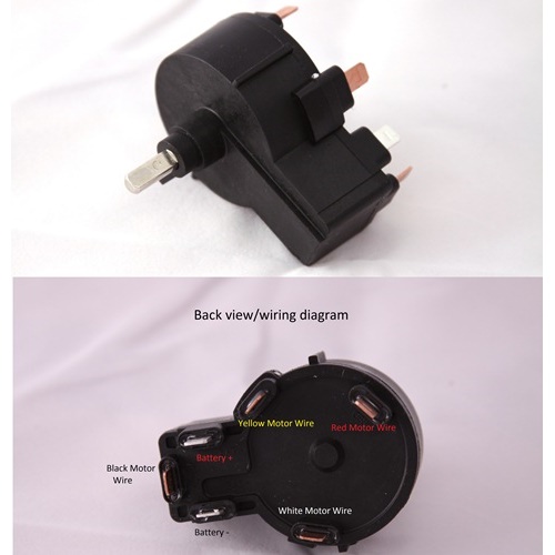
This is where organization is key. The 5-speed switch will have several wires connected to it. The number and color of wires can vary slightly by model year, but generally, you’ll see a main power input wire and several output wires corresponding to the different speeds and reverse.
- Take Photos: Before disconnecting any wires, take clear, well-lit photos of the existing wiring configuration from multiple angles. This will be an invaluable reference when connecting the new switch.
- Label Wires (If Necessary): If you’re concerned about remembering the connections, use a marker to label each wire with its corresponding terminal number or position on the old switch. Sometimes, the new switch may have different terminal numbering, so comparing it to your photos will be crucial.
- Disconnect Wires: Carefully disconnect each wire from the old switch.
- Spade Connectors: Many switches use spade connectors that simply pull off the terminals. Use needle-nose pliers if they are tight, but avoid pulling directly on the wire itself.
- Screw Terminals: Some switches may have small screws holding the wires in place. Unscrew these to release the wires.
- Soldered Connections: In rare cases, older switches might have soldered connections. If this is the case, you’ll need a soldering iron to de-solder and re-solder the connections. However, most DIY-friendly Endura switches use simpler connectors.
- Remove the Old Switch: Once all wires are disconnected, the old switch itself is usually secured by a nut on the outside of the control head, or it may simply press-fit into a slot. Unscrew the retaining nut (if present) and carefully remove the old switch from the control head.
Step 4: Installing and Wiring the New Switch
Now it’s time to install your replacement switch.
- Mount the New Switch: Insert the new 5-speed switch into the opening in the control head. Ensure it’s oriented correctly, aligning any tabs or keyways. If there’s a retaining nut, tighten it to secure the switch.
- Connect the Wires: This is the most critical part. Refer to your photos and any labels you made.
- Match Wire Colors/Positions: Connect each wire to the corresponding terminal on the new switch. Pay close attention to matching the old configuration precisely. Even if the terminal numbers on the new switch are different, the wire colors and their original positions relative to the “off” position are what matter.
- Secure Connections:
- Spade Connectors: Ensure spade connectors are pushed firmly onto the terminals. Give them a gentle tug to confirm they are secure.
- Screw Terminals: If your new switch uses screw terminals, insert the bare wire end and tighten the screw securely. Avoid overtightening.
- New Wires/Crimping: If your new switch came with pigtails or requires you to cut and re-crimp, ensure you strip about 1/2 inch of insulation from the wire end. Use a crimping tool and appropriate electrical connectors (e.g., butt connectors if joining two wire ends, or new spade connectors if attaching to terminals). Crimp them firmly, ensuring a strong mechanical and electrical connection.
- Heat Shrink/Tape: After crimping, slide heat shrink tubing over the connection and heat it with a heat gun until it shrinks tightly, providing insulation and weather protection. If using electrical tape, wrap it tightly and securely around the connection.
- Dielectric Grease (Optional): Before pushing on spade connectors or tightening screw terminals, apply a small dab of dielectric grease to the metal contacts. This helps prevent corrosion and ensures a good electrical connection.
Step 5: Testing the New Switch (Pre-Reassembly)
Before buttoning everything up, it’s highly recommended to perform a quick test.
- Reconnect Batteries (Briefly): Carefully reconnect the positive and negative battery cables to your boat’s battery.
- Test Functionality: With the propeller clear of obstructions and water, slowly rotate the new speed switch through all its forward and reverse settings.
- Does the motor turn on and off correctly?
- Does it engage all five forward speeds and three reverse speeds?
- Does the speed increase/decrease as expected with each detent?
- Does it turn off completely in the “Off” position?
- Listen and Observe: Listen for any unusual sounds or smells. If anything seems wrong, immediately disconnect the battery and re-check your wiring.
- Disconnect Batteries Again: Once you’ve confirmed the switch is working, immediately disconnect the battery cables again before proceeding to reassembly.
Step 6: Reassembling the Control Head
- Route Wires Neatly: Ensure all wires are tucked neatly inside the control head and are not pinched or crimped as you bring the two halves together.
- Reassemble Control Head Halves: Carefully align the two halves of the control head and gently press them back together.
- Reinstall Control Head Screws: Secure the control head halves by reinserting and tightening all the Phillips head screws you removed earlier. Do not overtighten.
- Reinstall Speed Knob: Place the speed knob back onto the switch shaft, ensuring it aligns with the “Off” position when the switch is in the off position. Reinsert and tighten the small screw that secures the knob.
Step 7: Final Test and Ready for the Water!
- Reconnect Batteries: Once everything is fully reassembled, reconnect the positive and negative battery cables to your boat’s battery.
- Final Test: Perform a thorough test of all speeds, forward and reverse, to ensure everything is working perfectly.
- Clean Up: Clean up any tools and dispose of the old switch.
Troubleshooting Common Issues:
- Motor Still Not Working:
- Double-check all wire connections. A loose connection is a common culprit.
- Ensure the battery is fully charged.
- Check the circuit breaker or fuse (if your boat has one) for the trolling motor.
- Verify you have the correct replacement switch for your model.
- Only Certain Speeds Working:
- This usually indicates a faulty connection to the wires for the non-working speeds. Re-inspect those specific connections.
- Less common, but possible, a manufacturing defect in the new switch itself.
- Propeller Not Turning (but motor hums):
- Check for fishing line or debris wrapped around the propeller shaft.
- Inspect the prop pin for damage or shearing.
- This is usually a prop-related issue, not a switch issue.
- Switch Feels Loose or Jumpy:
- Ensure the retaining nut on the switch (if applicable) is fully tightened.
- Make sure the control head screws are snug.
By following these detailed steps, you can confidently replace the 5-speed switch on your Minn Kota Endura trolling motor, restoring its functionality and extending its lifespan. A little DIY effort can save you money and keep you fishing without interruption! For diagrams and specific part numbers for your Minn Kota Endura, always visit ReelSchematic.com’s extensive library of parts and schematics.